2.3 Physics notes
advertisement
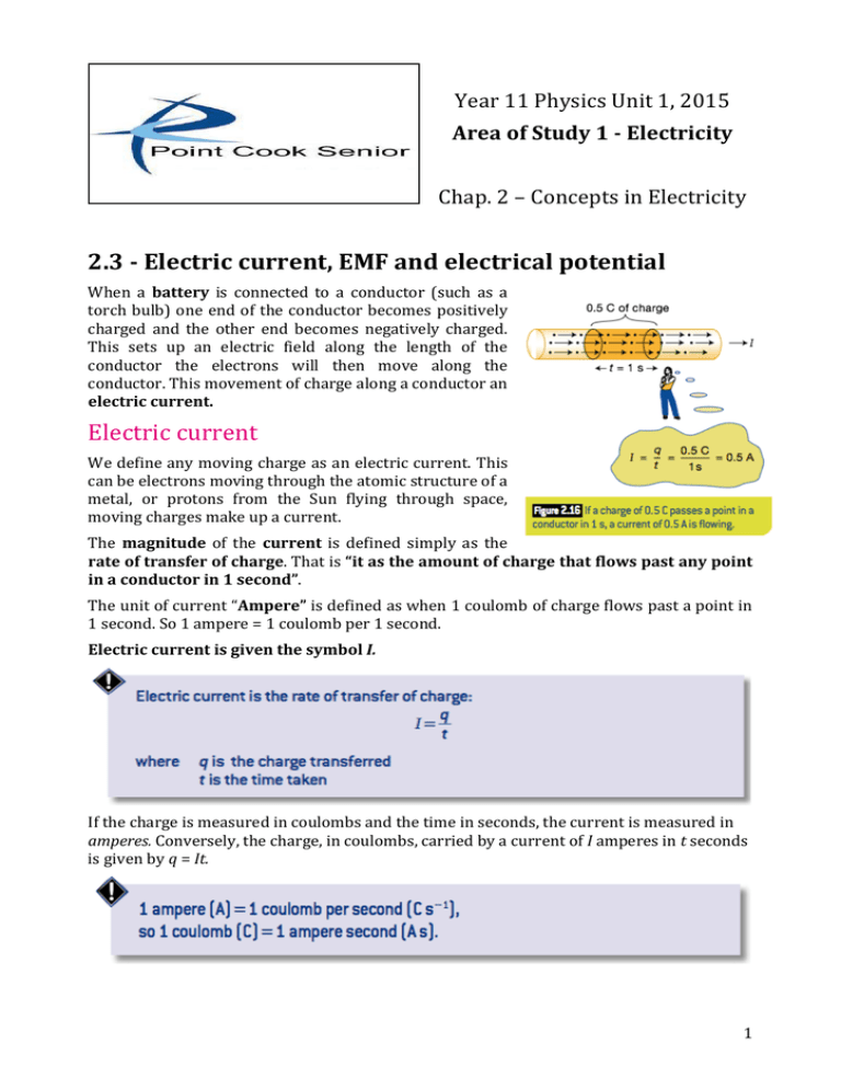
Year 11 Physics Unit 1, 2015 Area of Study 1 -­‐ Electricity Chap. 2 – Concepts in Electricity 2.3 -­‐ Electric current, EMF and electrical potential When a battery is connected to a conductor (such as a torch bulb) one end of the conductor becomes positively charged and the other end becomes negatively charged. This sets up an electric field along the length of the conductor the electrons will then move along the conductor. This movement of charge along a conductor an electric current. Electric current We define any moving charge as an electric current. This can be electrons moving through the atomic structure of a metal, or protons from the Sun flying through space, moving charges make up a current. The magnitude of the current is defined simply as the rate of transfer of charge. That is “it as the amount of charge that flows past any point in a conductor in 1 second”. The unit of current “Ampere” is defined as when 1 coulomb of charge flows past a point in 1 second. So 1 ampere = 1 coulomb per 1 second. Electric current is given the symbol I. If the charge is measured in coulombs and the time in seconds, the current is measured in amperes. Conversely, the charge, in coulombs, carried by a current of I amperes in t seconds is given by q = It. 1 Worked example 2.3A Determine the charge that has flowed through a torch battery producing a current of 300 mA if it has been left on for 20 minutes. The direction of current In the case of a river, the direction of the current is clear; it is the direction of flow of the water. Unlike water, however, electric charge can be either positive or negative. So what is the direction of an electric current? We define the direction of an electric current as the direction of transfer of positive charge. However, positive charge can be transferred to the right, let’s say, either by moving positive charge to the right, or by moving negative charge to the left. In a metal wire, for example, a positive current to the right is carried by electrons moving to the left. On the other hand, in a fluorescent tube a positive current to the right is carried both by positive ions moving to the right and by electrons moving to the left. Because the electrons in a wire actually move in the opposite direction to the current, the terms electron current and conventional current are sometimes used to distinguish between them. It is important to remember, however, that current is the rate of transfer of positive charge. Figure 2.19 A current to the right might result either from positive charges moving in the direction of the current, from negative charges moving in the opposite direction, or both at once. Figure 2.20 (a) Current flows around a circuit from the positive terminal of the battery to the negative. In the connecting wires the current is carried by electrons travelling in the opposite direction. (b) the beam of electrons travelling down a cathode ray tube in a television set produces a positive current in the opposite direction. 2 Now complete Questions 1 to 7 on page 58 EMF and electric potential In order to drive a current around an electric circuit the charges must be given energy. A battery or generator is the usual source of this energy. Another increasingly common source of electrical energy is the photovoltaic cell, or solar cell. These devices are all referred to as sources of EMF. The letters EMF stands for Electro Motive Force. (EMF is still used although it is not accurate, it is the energy given to the charges rather than the force on them) It may help understand EMF by thinking of the Van de Graaff generator (see Figure 2.4). The source of energy in this case is very obvious. The motor is pushing the charges on the rubber belt up against the electrostatic repulsion of the charges already on the dome. The more charge already on the dome, the greater the force, and hence the greater the work that has to be done to bring more charge to the dome. EMF can be visualised as a ‘concentration of charge’. The more charges put on the dome, the more concentrated they become and the greater the force of repulsion between them. The work done pushing the charges together (by the motor in this case) is stored as electrical potential energy. The electrical energy can be used when the charges are allowed to fly apart again. In the case of the Van de Graaff this potential energy is converted into kinetic energy, as it sparks, and as the charges collide with the air molecules it is turned into heat, light and sound energy. EMF is defined as the amount of work done for each unit of charge in this process of charge concentration. Because it is, therefore, actually the ‘electric potential energy per unit charge’, this quantity is most often abbreviated simply to electric potential or just potential. The SI unit for potential is joule per coulomb. One joule per coulomb is given the name volt, in honour of Alessandro Volta, the inventor of the first chemical battery. This means that if you have an EMF of 9 V each 1C of charge is given 9 J of energy, or in general: Energy E = V x q, where V is in Volts and q is the charge in C. 3 Worked example 2.3B The alternator of a car being driven at night with the headlights on, is producing a 50 A current at an EMF of 12 V. a How many coulombs of charge flow from the alternator each second? b How many joules of energy does each coulomb of charge obtain? c How many joules of energy does the alternator produce each second? d Where does this energy go? Electric circuits and potential difference Any electric circuit consists of at least one source of EMF, conductors that carry current and the various circuit elements. Consider a simple torch circuit: a battery, a switch and a bulb all connected by wires. The current from the battery goes from the positive terminal to the bulb and then via the switch back to the base of the battery, which acts as the negative terminal. (Remember how we defined the direction of current early). When a battery is connected in a circuit, it produces a potential difference; that is, a difference in the potential energy of the charges in the conductors connected to its terminals. While the switch is off, All the conductors on one side of the switch will have the same positive potential and all those on the other side the same negative potential. 4 Figure 2.24 the electric field and the potential around a circuit are related. (a) In an open circuit there is no potential drop around the circuit and no electric field (except at the switch). (b) In the closed circuit charge flows as the result of an electric field. As it flows it loses potential. Where the conductor is narrow the field is ‘squeezed’ and becomes stronger, thus the charges are pushed harder. the potential also drops more quickly through the narrow region as more work is done and potential energy lost. The potential difference across a circuit element is the potential energy lost by each unit of charge in that element. The potential difference, sometimes called potential drop or just p.d., across a circuit element is written ∆V, the ∆ representing the fact that there is a change of potential. In practice, the ∆ is often omitted as there is rarely a need to refer to anything other than a change of potential. As ∆V is the energy lost by one unit of charge, a charge of q coulomb will lose q∆V joules of potential energy as it goes through a potential difference of ∆V. Worked example 2.3C The potential difference across a torch bulb is found to be 2.7 V. the current flowing through itis0.2A. A how much charge flows through the torch in 1 minute? B how much energy is lost by this charge? Now complete Questions 8 to 14 on page 58 5
