function generator
advertisement

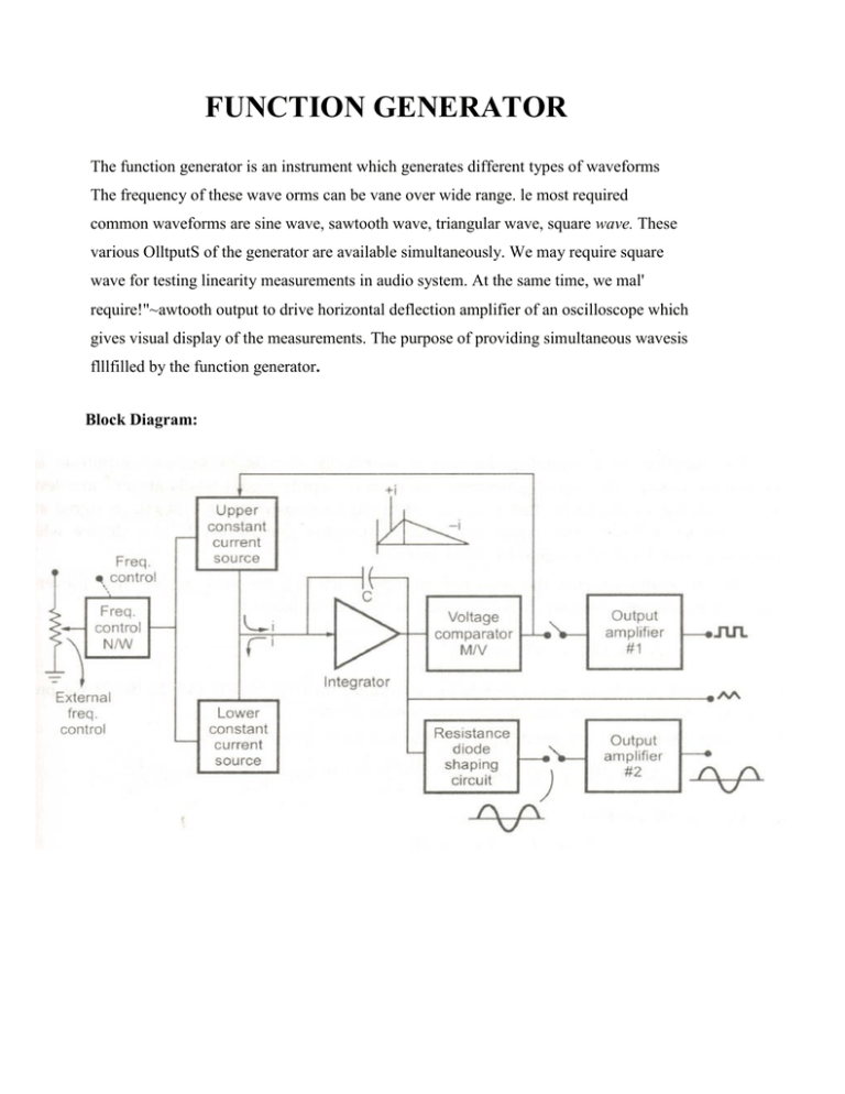
FUNCTION GENERATOR The function generator is an instrument which generates different types of waveforms The frequency of these wave orms can be vane over wide range. le most required common waveforms are sine wave, sawtooth wave, triangular wave, square wave. These various OlltputS of the generator are available simultaneously. We may require square wave for testing linearity measurements in audio system. At the same time, we mal' require!"~awtooth output to drive horizontal deflection amplifier of an oscilloscope which gives visual display of the measurements. The purpose of providing simultaneous wavesis flllfilled by the function generator. Block Diagram: The frequency controlled voltage is used to regulate two current sources namely upper current source and lower current source. The upper current source supplies constant current to an integrator. The output voltage of integrator then increases linearly with time. If the current, charging the capacitor increases or decreases, the slope of output voltage increases or decreases respectively. Hence this controls frequency. The voltage comparator multivibrator circuit changes the state of the network when the output voltage of integrator equals the maximum predetermined upper level. Because of this change in state, the upper current source is removed and the lower current source is switched ON. This lower current source supplies opposite current to the integrator circuit. The output of integrator decreases linearly with time. When this output voltage equals maximum predetermined upper level on negative side, the voltage comparator multivibrator again changes the condition of the network by switching OFF the lower current source and switching ON the upper current source. The output voltage of the integrator has triangular waveform. The frequency of this triangular waveform is determined by the magnitudes of the currents supplied by upper current source and lower current source. To get square wave, the output of the integrator is passed through comparator. The voltage comparator delivers square wave output voltage·of same frequency as that of input triangular waveform. The sine wave is derived from triangular wave. The triangular wave is synthesised into sine wave using diode resistance network. In this shaper circuit, the slope of triangular wave is changed as its arr'plitude changes. This results in a sine wave with less than 1% distortion. The two output amplifiers provide two simultaneous, individually selected outputs of any of the waveform functions. The function of a signal generators is to supply signals of known amplitude and known frequency. The signal generators are used to supply signal levels at very low levels for the testing of receivers. But it is very difficult to measure and calibrate a signal at a very low level. Thus attenuators are used in function generators. It is a device which reduces power level of a signal by fixed amount. Source : http://elearningatria.files.wordpress.com/2013/10/ece-iii-electronic-instrumentation-10it35notes.pdf


