Installation Environment
Before Installation:
FacePass Pro
The FacePass Pro working temperature:0℃---45℃,working humidity:20%---80%
Direct sunlight would cause great impact on the face recognition performance. So the device is not allowed to be installed
Standalone Facial Recognition System
Quick Guide
outside. Please install the device indoor and avoid strong light shining straight into the camera.
(V1.0)
Installation Steps
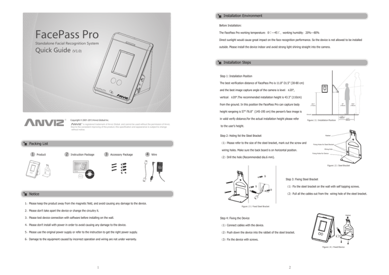
Step 1: Installation Position
The best verification distance of FacePass Pro is 11.8’’-31.5’’ (30-80 cm)
Face
Stan
da
lone
Pass
Facia
l Re
cogn
and the best image capture angle of the camera is level:±20°,
Pro
ition
Syste
m
vertical:±20°.The recommended installation height is 43.3’’ (110cm)
from the ground. In this position the FacePass Pro can capture body
height rangeing is 57’’-76.8’’ (145-195 cm) the person’s face image is
in valid verify distance.For the actual installation height please refer
Copyright © 2001-2013 Anviz Global Inc.
is registered trademark of Anviz Global. and cannot be used without the permission of Anviz.
Due to the consistent improving of the product, this specification and appearance is subject to change
without notice.
43.3”
(110cm)
Ground
11.8”
(30cm)
Figure(1) Installation Position
1 Product
3 Accessory Package
4 Wire
31.5”
(80cm)
Rabbet
(1)Please refer to the size of the steel bracket, mark out the screw and
2 Instruction Package
76.8”
(195cm)
to the user’s height.
Step 2: Holing fot the Steel Bracket
Packing List
57”
(145cm)
Fixing Holes for Steel Bracket
Wiring Hole
wiring holes. Make sure the back board is on horizontal position.
Fixing Holes for Device
(2)Drill the hole (Recommended dia.6 mm).
FacePass Pro
Standalone Facial Recognition System
Quick Guide
Figure(2) Steel Bracket
(V1.0)
FacePas
s Pro
Standalone
Facial
Recognition
System
Copyright © 2001-2013 Anviz Global Inc.
is registered trademark of Anviz Global. and cannot be used without the permission of Anviz.
Due to the consistent improving of the product, this specification and appearance is subject to change
without notice.
FOR
EN
CH ...
windows
Windows 98
Windows 2000
Windows XP
COMPACT
CD-ROM
Windows Vista
Windows 7
EM Card
Step 3: Fixing Steel Bracket
Copyright ANVIZ All rights reserved.
http://www.anviz.com
(1)Fix the steel bracket on the wall with self tapping screws.
Notice
(2)Pull all the cables out from the wiring hole of the steel bracket.
1、Please keep the product away from the magnetic field, and avoid causing any damage to the device.
Figure(3) Fixed Steel Bracket
2、Please don’t take apart the device or change the circuitry it.
Rabbet
3、Please test device connection with software before installing on the wall.
Step 4: Fixing the Device
4、Please don’t install with power in order to avoid causing any damage to the device.
(1)Connect cables with the device.
5、Please use the original power supply or refer to the instruction to get the right power supply.
(2)Push down the device into the rabbet of the steel bracket.
6、Damage to the equipment caused by incorrect operation and wiring are not under warranty.
(3)Fix the device with screws.
Figure(4) Fixed Device
1
2
ID Recognition
Enroll User
1
Power on the device
to enter Input Page.
Press
to Admin
verification page.
2
3
4
Input default password
“12345”and press
to enter Main Menu
Page.
Click “User”option to
User Manage Page.
Click “New”to enter User
Enroll Page.
1
2
There is a
button in
the Face Recognition Page.
Press it to ID Recognition
Page.
3
Input User ID and Password
to verify the User ID
in the input box.
and Password.
to cancel verification
and back to Input page.
4
ID and Password verification
succeed. The camera captures
a current image display on
the LCD.
RF
ID
Card Recognition
5
6
Click input box to input
Name, ID and Password.
The device provides letters
input when click “Name”
and the click
to next
enroll steps.
7
Press“Card”to ID card
enroll page.
8
Press“Read Card”, the
device waiting for swipe
card at the card reader
area. Then the Card will
display on the device.
Press
back to User
Enroll Page.
Press“Enroll”to capture
user face image. Before
capture user face the device
will prompt on the screen.
Face
Stand
alone
1
Pass
Facia
l Reco
Pro
gnitio
n Syste
m
3
2
The Card Recognition, the
device must stay on the
Input page.
Swiped the registered card on the card redaer area. ID and Password verification
succeed. The camera captures
a current image display on
the LCD.
FacePass Pro Structure
LEDs
Notice:
9
During face image capturing process, please keep your face in the
yellow frame and move face forward and backward slightly till enrolling
successfully.
Yellow frame: The valid recognition area;
Blue frame: The valid image capturing area;
Red bar: The duration of the device in capture statues.
Green Bar: The face template capture schedule.
The
button use to change the
camera image display on the LCD.
The
button use to cancel the
face image capturing process.
Touch Screen
Dual Carmers
Power Switch
Card Reader Area
Restart
USB Flash Drive Port
Face Recognition
Face
Stan
dalon
Pass
e Fa
cial
Pro
Reco
gnitio
n Sy
stem
Power
1
If enable body induction
in the device, it will
automatically switch to
Face Recognition Page
when user stands in front
of the device.
3
According to the device
instruction ,please keep
your face in the yellow
frame.
3
4
Face verification succeed.
Relay
Notice:
The Mini USB Port use
to factory debug mode,
can not communication
with software.
TCP/IP
Min USB Port
4
NC
COM
NO
In the Input page ,click
to enter Face
Recognition Page.
2


