TJERNLUND PRODUCTS, INC.
1601 Ninth Street • White Bear Lake, MN 55110-6794
PHONE (800) 255-4208 • (651) 426-2993 • FAX (651) 426-9547
Visit our web site • www.tjernlund.com
INSTALLATION INSTRUCTIONS FOR ND-1 (950-2043) POST PURGE BURNER KIT
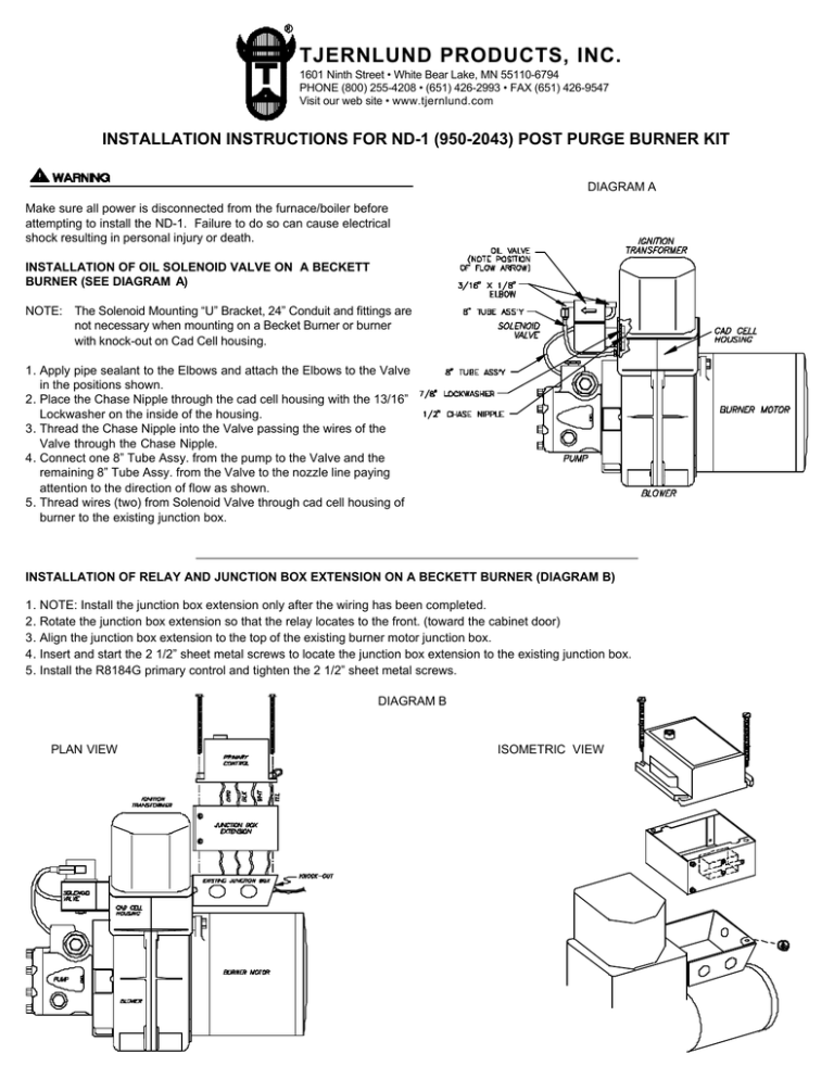
DIAGRAM A
Make sure all power is disconnected from the furnace/boiler before
attempting to install the ND-1. Failure to do so can cause electrical
shock resulting in personal injury or death.
INSTALLATION OF OIL SOLENOID VALVE ON A BECKETT
BURNER (SEE DIAGRAM A)
NOTE: The Solenoid Mounting “U” Bracket, 24” Conduit and fittings are
not necessary when mounting on a Becket Burner or burner
with knock-out on Cad Cell housing.
1. Apply pipe sealant to the Elbows and attach the Elbows to the Valve
in the positions shown.
2. Place the Chase Nipple through the cad cell housing with the 13/16”
Lockwasher on the inside of the housing.
3. Thread the Chase Nipple into the Valve passing the wires of the
Valve through the Chase Nipple.
4. Connect one 8” Tube Assy. from the pump to the Valve and the
remaining 8” Tube Assy. from the Valve to the nozzle line paying
attention to the direction of flow as shown.
5. Thread wires (two) from Solenoid Valve through cad cell housing of
burner to the existing junction box.
INSTALLATION OF RELAY AND JUNCTION BOX EXTENSION ON A BECKETT BURNER (DIAGRAM B)
1. NOTE: Install the junction box extension only after the wiring has been completed.
2. Rotate the junction box extension so that the relay locates to the front. (toward the cabinet door)
3. Align the junction box extension to the top of the existing burner motor junction box.
4. Insert and start the 2 1/2” sheet metal screws to locate the junction box extension to the existing junction box.
5. Install the R8184G primary control and tighten the 2 1/2” sheet metal screws.
DIAGRAM B
PLAN VIEW
ISOMETRIC VIEW
DIAGRAM C
Make sure all power is disconnected from the furnace/boiler before
attempting to install the ND-1. Failure to do so can cause electrical
shock resulting in personal injury or death.
INSTALLATION OF OIL SOLENOID VALVE ON NON-BECKETT
BURNERS
1. Apply pipe sealant to the Solenoid Elbows, insert and tighten to position necessary for oil tubing.
2. Place the metal “U” Solenoid Bracket around Solenoid Valve.
3. Insert 1/2” Chase Nipple to Solenoid Valve and tighten.
4. Using screws provided, attach Solenoid to appliance wall. NOTE:
Solenoid tubing is 8” long. If Oil Tubing does not reach pump and
burner chamber the installer must provide a means of mounting the
Solenoid Bracket on an extension. If mounting on a boiler attach
Solenoid to exterior boiler wall with the 3/8” self tapping screws using
the larger holes in Bracket, (See Diagram C). If mounting on a furnace install Solenoid on interior wall with the 3/8” self tapping screws
using the smaller holes in Bracket, (See Diagram D).
5. Connect one 8” Tube Assy. from the pump to the Valve and the
remaining 8” Tube Assy. from the Valve to the nozzle line paying
attention to the direction of flow as shown, (See Diagram E).
6. The 24” long 3/8” diameter metal Conduit will have to be added to
accommodate the placement of the Solenoid Valve on the wall of
the appliance.
7. Thread wires through metal conduit for connection to primary control.
INSTALLATION OF RELAY AND JUNCTION BOX EXTENSION ON
NON-BECKETT BURNERS (DIAGRAM E)
1. NOTE: Install the junction box extension only after the wiring has
been completed.
2. Rotate the junction box extension so that the relay locates to the
front. (toward the cabinet door)
3. Align the junction box extension to the top of the existing burner
motor junction box.
4. Insert and start the 2 1/2” sheet metal screws to locate the junction
box extension to the existing junction box.
5. Install the primary control and tighten the 2 1/2” sheet metal screws.
DIAGRAM E
DIAGRAM D
ELECTRICAL WIRING CONNECTIONS
The electrical contact ratings for the Oil Solenoid Valve and the Relay are as follows:
OIL SOLENOID VALVE: 0.115 Amps at 120 VAC
RELAY: 0.10 Amps at 120 VAC (Coil), 12 Amps (full load) at 124 VAC (Contacts), 60 Amps (locked rotor) at 125 VAC (Contacts)
Make sure all power is disconnected from the furnace/boiler before attempting to install the ND-1. Failure to do so can cause electrical shock
resulting in personal injury or death.
All wiring from the to the post purge kit must be appropriate Class 1 wiring as follows: installed in rigid metal conduit, intermediate metal conduit,
rigid non-metallic conduit, electrical metallic tubing, Type MI Cable, Type MC Cable, or be otherwise suitably protected from physical damage.
SIDESHOT® WIRED WITH STANDARD HONEYWELL ST9103 CONTROL & BURNER MOTOR POST PURGE
SIDESHOT
TERMINAL
STRIP
FURNACE
TERMINAL
STRIP
THERMOSTAT
TERMINAL
STRIP
HST-SERIES WIRED WITH HONEYWELL ST9103 CONTROL AND BURNER MOTOR POST PURGE KIT
SIDESHOT® OR HST-SERIES WIRED WITH BURNER MOTOR POST PURGE KIT
SIDESHOT® OR HST-SERIES WIRED WITH PHELON CONTROL AND BURNER MOTOR POST PURGE KIT
REPLACEMENT PARTS
OIL SOLENOID
115V RELAY
REV. 1/96
PART# 950-0690
PART# 950-0695
Copyright © 1995 Tjernlund Products, Inc. All rights reserved.
P/N 8504004


