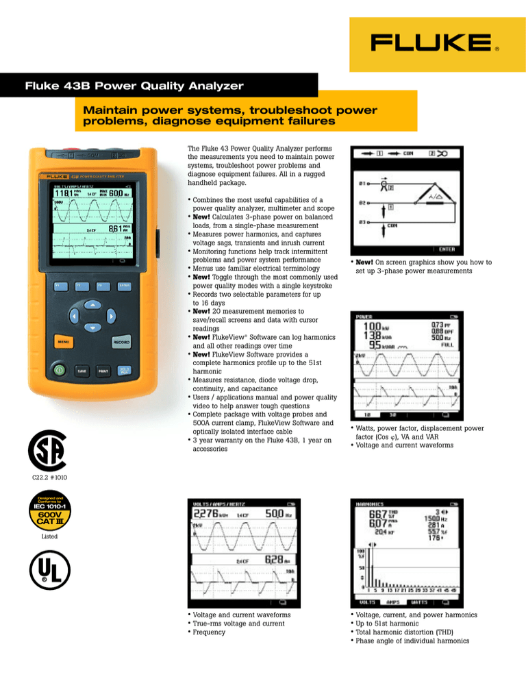
Fluke 43B Power Quality Analyzer
Maintain power systems, troubleshoot power
problems, diagnose equipment failures
The Fluke 43 Power Quality Analyzer performs
the measurements you need to maintain power
systems, troubleshoot power problems and
diagnose equipment failures. All in a rugged
handheld package.
• Combines the most useful capabilities of a
power quality analyzer, multimeter and scope
• New! Calculates 3-phase power on balanced
loads, from a single-phase measurement
• Measures power harmonics, and captures
voltage sags, transients and inrush current
• Monitoring functions help track intermittent
problems and power system performance
• Menus use familiar electrical terminology
• New! Toggle through the most commonly used
• New! On screen graphics show you how to
set up 3-phase power measurements
power quality modes with a single keystroke
• Records two selectable parameters for up
to 16 days
• New! 20 measurement memories to
•
•
•
•
•
•
save/recall screens and data with cursor
readings
New! FlukeView® Software can log harmonics
and all other readings over time
New! FlukeView Software provides a
complete harmonics profile up to the 51st
harmonic
Measures resistance, diode voltage drop,
continuity, and capacitance
Users / applications manual and power quality
video to help answer tough questions
Complete package with voltage probes and
500A current clamp, FlukeView Software and
optically isolated interface cable
3 year warranty on the Fluke 43B, 1 year on
accessories
• Watts, power factor, displacement power
factor (Cos ), VA and VAR
• Voltage and current waveforms
C22.2 #1010
Designed and
Conforms to
IEC 1010-1
600V
CAT III
Listed
R
• Voltage and current waveforms
• True-rms voltage and current
• Frequency
• Voltage, current, and power harmonics
• Up to 51st harmonic
• Total harmonic distortion (THD)
• Phase angle of individual harmonics
Specifications
Accuracies are stated as ± (percentage of
reading + counts) without probes unless
otherwise noted.
Input Characteristics
Input impedance
Voltage rating
Volt / Amps / Hertz
True-rms voltage (AC+DC)
True-rms current (AC+DC)
Frequency
CF Crest Factor
Power
W, VA, VAR Reactive Power
1-phase and 3-phase, 3
conductor balanced loads
PF Power Factor
DPF Displacement Power Factor
• Continuously measure volts and amps on a
cycle-by-cycle basis for up to 24 hours
• Use cursors to read time and date of sags
and swells
Hz Frequency fundamental
Harmonics
Volts, Amps, Watts
Specifications are valid for signals with a
fundamental between 40 and 70 Hz.
Ranges
1 MΩ, 20 pF
600 Vrms, CAT III
Accuracy
5.000 V, 50.00 V, 500.0 V, 1250 V*
50.00 A, 500.0 A, 5.000 kA, 50.00 kA, 1250 kA
10.0 Hz to 15.0 kHz
1.0 to 10.0
±
±
±
±
250 W 2.50 kW, 25.0 kW, 250kW, 2.50 MW,
25 MW, 250 MW, 625 MW, 1.56 GW
± (2 % + 6 counts) Total Power
± (4 % + 4 counts) Fundamental
Power
± 0.04
not specified
± 0.04
± 0.03
± (0.5 % + 2 counts)
0.00 to
0.00 to
0.25 to
0.90 to
40.0 to
1.00
0.25
0.90
1.00
70.0 Hz
Fundamental
2 to 31st Harmonic
32 to 51st Harmonic
Frequency of fundamental
Phase
K-Factor (Amps & Watts)
THD
Sags & Swells
Recording times (selectable)
Vrms actual, Vrms max,
min (AC + DC)
• Catch voltage transients and waveform
distortion
• Catch and save up to 40 transients
• Correlate the cause of transients with time
and date stamps
Arms actual, Arms max,
min (AC + DC)
Recording
Recording times (selectable)
Parameters
V/A/Hz
Power
Harmonics
Ohms
Temperature
Scope
Transients
Minimum pulse width
Useful bandwidth input 1
Number of transients
Voltage threshold settings
Reference signal
Vpeak min, Vpeak max at cursor
*Rated 600V CAT III
40 Hz to 70 Hz
Volt & Amps (between Fund. & Harmonic)
Watts (between Volt Fund. & Amps
Harmonic )
1.0 to 30.0
0.00 to 99.99
4 min to 16 days
5.000 V, 50.00 V 500.0 V, 1250 V*
(1 % + 10 counts)
(1 % + 10 counts)
(0.5 % +2 counts)
(5% + 1 count)
V,A ± (3 % + 2 counts),
W ± (5 % + 2 counts)
V,A ± (5 % + 3 counts),
W ± (10 % + 10 counts)
V,A ± (15 % + 5 counts),
W ± (30 % + 5 counts)
± 0.25 Hz
2nd (± 3°) … 51st (±15°)
Fund (± 5°) … 51st (±15°)
±10 %
± (3% + 8 counts)
Readings ±(2% +10 counts)
Cursor readings ± (2% + 12 counts)
Cursor Readings Average ±(2%
+10 counts)
50.00 A, 500.0 A, 5.000 kA, 50,00 kA
4 min to 16 days
Choose one or two parameters from one of the groups below
Line Voltage, Current, Frequency
Watts, VA, VAR, PF, DPF, Frequency
THD, Volts (Fund. & Harmonic), Amps(F&H) Watts(F&H) Freq.(H), %(H) of total, Phase(H), KF
Ohms, Diode, Continuity, Capacitance
°C or °F
DC Voltage, DC Current, AC Voltage, AC Current, Frequency, Pulse Width + or -,
Phase, Duty cycle + or -, Peak max, Peak min, Peak min-max, Crest Factor
40 ns
DC to 1 MHz (with test leads TL24)
40
20%, 50%, 100%, 200% above or below reference signal
After START, the Vrms and frequency of the signal are measured. From these
data a pure sinewave is calculated as reference for threshold setting.
10 V, 25 V, 50 V, 125 V, 250 V, 500 V, 1250 V
± 5% of full scale
®
Inrush Current
Ranges
Accuracy
Current ranges (selectable)
1 A, 5 A, 10 A, 50 A, 100 A, 500 A, 1000 A
Inrush times (selectable)
l s, 5 s, 10 s, 50 s, 100 s, 5 min
Cursor readings
A peak max at cursor 1 and cursor 2
± 5% of full scale
Time between cursors**
4 to 235 pixels
± (0.2% + 2 pixels)
Scope, dual channel scope with measurement reading
Input impedance
Input 1
1 MΩ//12 pF; with BB120: 20 pF
± 2 pF; with BB120 ±3 pF
Input 2
1 MΩ//10 pF; with BB120: 18 pF
± 2 pF; with BB120 ±3 pF
Vertical
Voltage ranges
50 mV/div to 500V/div
± (1% + 2 pixels)
Vertical sensitivity, resolution
5 mV/div to 500V/div, 8 bit (256 levels)
Bandwidth input 1 (voltage)
DC to 20 MHz at inputs, or with BB120 and VPS100-R probe (Opt);
1 MHz with TL24 Leads
Bandwidth input 2 (current)
DC to 15 kHz at inputs
10 kHz with 80i-500s Current Clamp
Coupling
DC, AC (10 Hz -3 dB)
Horizontal
TimeBase modes
Normal, roll, single
TimeBase ranges
60 s/div to 20 ns/div
± (0.4% + 1 pixel)
Sampling rate
25 MS/s
Record length
512 per channel
(min / max samples)
Trigger source
Input 1 or Input 2 or Automatic selection
Trigger mode
Automatic Connect-and-View™, Free Run,
Single Shot.
Connect-and-View™
Advanced automatic triggering that recognizes signal patterns and automatically
adjusts triggering, timebase and amplitude. Automatically displays stable pictures
of complex and dynamic signals like motor drive and control signals.
Pre-trigger
Up to 10 divisions
Measurement readings,
Volts & Amps (DC, AC, AC + DCrms, Peak max, Peak min, Peak min / max ),
per channel selectable
Frequency, Duty cycle + or - , Phase, Pulse Width + or -, Crest factor
Ohms, Diode, Continuity, Capacitance
Ohms
500.0 Ω 5.000 kΩ, 50.00 kΩ, 500.0 kΩ,
± (0.6% +5 counts)
5.000 MΩ, 30.00 MΩ
Diode voltage
0 to 3.000 V
± (2% +5 counts)
Continuity, shorts > 1 ms
Beeper on at < 30Ω ± 5Ω,
Capacitance
50.00 nF, 500.0 nF, 5.000 µF, 50.00 µF,
±(2% +10 counts)
500.0 µF
Temperature***
-100.0 °C to 400.0 °C,
±(0.5% +5 counts)
-200.0 °F to 800.0 °F
Max current, max open circuit volt. 0.5 mA, < 4 V (all functions above)
Memory
Number of screens
20
Optical Isolated RS-232 Interface
To printer
Supports HP LaserJet™, DeskJet, Epson FX/LQ and Postscript printers with
optional PAC91 Printer Adapter Cable
To PC
FlukeView® Power Quality Analyzer software with PM9080 Interface
Adapter included
FlukeView® Power Quality Software
Hardware requirements
PC or 100% compatible with Windows® 95, 98, Me, 2000, NT4.0.
• Inrush current up to 500A with supplied
current probe
• Use cursors to measure inrush current timing
• Connect-and-View™ scope for quick
waveform display
• Voltage and current channels
• 20MHz bandwidth with optional 10:1 voltage
probe. 15kHz on current channel with
optional current clamp
** 1 pixel = inrush time/250
*** Requires optional temperature accessory
• FlukeView® Power Quality Analyzer software
(included)
• Capture measurement screens for
professional-looking reports
• Log readings to your computer disk drive
• Works with Windows word processing,
spreadsheet and analysis software
• Windows 95 / 98 / Me / 2000 / NT 4.0
General Specifications
Power
Line voltage adapter/battery charger included
Installed battery
Rechargeable NiCd pack (4 to 6 Vdc)
Operating time
4 hours
Charging time
4 hours (Fluke 43B OFF) 12 hours (Fluke 43B ON)
Refresh Cycle
8 to 14 hours (to keep NiCd battery capacity optimal)
Environmental
Temperature
0ºC to 50ºC (32ºF to 122ºF)
Environmental
MIL 28800E, Type 3, Class III, Style B
Enclosure
IP51 (dust, drip water proof)
Mechanical Data
Size (H x W x D)
232 x 115 x 50 mm (9.1 x 4.5 x 2 inches)
Weight
1.1 kg (2.5 lbs.) incl. battery pack
Safety
For measurements on 600 Vrms Category III installations, Pollution Degree 2 in accordance with
EN61010-1 (1993) (IEC1010-1)
ANSI/ISA S82.01-1994
CAN/CSA-C22.2 No. 1010.1-92
UL3111-1
Surge protection
6 kV on input 1 and 2
Floating measurements
600 Vrms from any terminal to ground
Warranty
3 years parts and labor on Fluke 43B, 1 year on accessories
Ordering Information
Optional Accessories
Fluke 43B Power Quality Analyzer
C789
80i-110s
i200s
i1000s
i2000flex
Included Accessories
Hard Case
Test Leads
Industrial Test Clips
Large Jaw Alligator Clips
Flat-tipped Slim-Reach™ Test
Probes
TP4
4 mm Round Slim-Reach™
Test Probes
80i-500s 500A AC Current Clamp
PM 9080 Optically Isolated RS232
Interface Adapter
BP120
Rechargeable Ni-Cd Battery
Pack (installed)
PM 8907 Line Voltage Adapter/Battery
Charger
SW43W
FlukeView® Power Quality
Analyzer Software for
Windows
FlukeView® Power Quality Analyzer
Users Manual
Shielded Banana-to-BNC Adapter
Users Manual / Application Guide
Power Quality CD-ROM
C120
TL24
AC20
AC85
TP1
Soft Carrying Case
100A AC/DC Current Probe
AC Current Clamp
1000A AC Current Clamp
Flexible 2000A AC Current
Probe
i3000s
Clamp-On AC Current Clamp
VPS100-R Red 10:1 Voltage Probe
(requires BB120, one
included)
BB120
Two Shielded Banana-toBNC Adapters
80TK
Thermocouple Module
80T-IR
Non Contact Infrared
Temperature Probe
80T-150U Universal Temperature Probe
PAC91
Parallel Printer Adapter
PM9087
Isolated Automotive Lighter
Plug Charging Adapter
TL20
63" Test Lead Set
TL21
Extension Lead Set
TL22
63" Right Angle Silicone Test
Lead Set
TL23F
Electrical Test Lead Set
TL23R
Electrical Test Lead Set
TL24
63" Right Angle/Straight
Silicone Test Leads
TL26A
60" 5-Way Test Lead Set
TL28A
63" Alligator Clip Test Lead
Set
TL71
Premium DMM Test Lead
Assembly
TL74
4 mm Diameter Test Leads
TL75
48" Hardpoint Test Lead Set
1
2
43B POWER QUALITY ANALYZER
F1
F2
F3
MENU
ENTER
RECORD
SAVE
PRINT
HOLD
RUN
Fluke. Keeping your world
up and running.
Fluke Corporation
PO Box 9090, Everett, WA USA 98206
Fluke Europe B.V.
PO Box 1186, 5602 BD
Eindhoven, The Netherlands
For more information call:
In the U.S.A. (800) 443-5853 or
Fax (425) 446-5116
In Europe/M-East/Africa (31 40) 2 675 200 or
Fax (31 40) 2 675 222
In Canada (800) 36-FLUKE or
Fax (905) 890-6866
From other countries (425) 446-5500 or
Fax (425) 446-5116
Web access: http://www.fluke.com/
©2001 Fluke Corporation. All rights reserved.
Trademarks are the property of their respective owners.
Printed in U.S.A. 4/2001 1266142 D-ENG-N Rev F
Printed on recycled paper.


