Accessories
Intrinsically safe repeater power supply
For applications in hazardous areas
Model IS Barrier
WIKA data sheet AC 80.14
Applications
■■ Chemical, petrochemical industry
■■ Oil, natural gas
■■ Machine building
Special features
■■ Input 0/4 ... 20 mA, supplying and non-supplying
■■ Suitable for SIL 2 per IEC 61508/IEC 61511
■■ Bidirectional HART® signal transmission
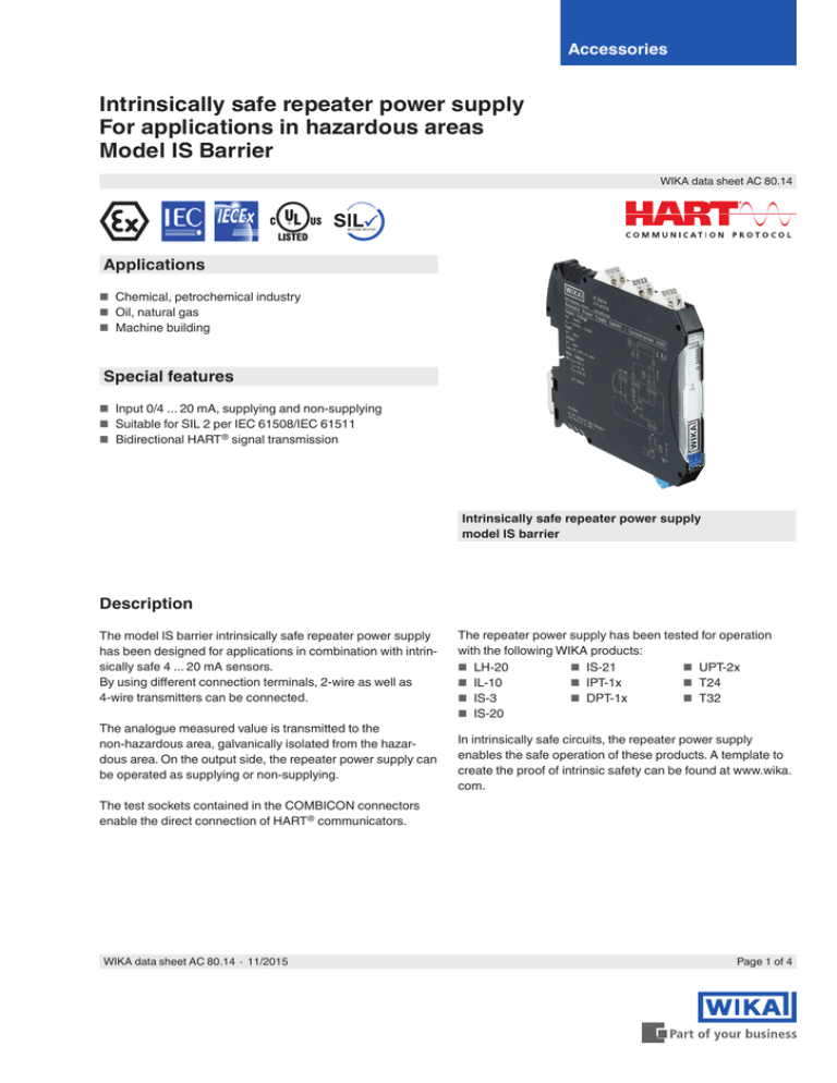
Intrinsically safe repeater power supply
model IS barrier
Description
The model IS barrier intrinsically safe repeater power supply
has been designed for applications in combination with intrinsically safe 4 ... 20 mA sensors.
By using different connection terminals, 2-wire as well as
4-wire transmitters can be connected.
The analogue measured value is transmitted to the
non-hazardous area, galvanically isolated from the hazardous area. On the output side, the repeater power supply can
be operated as supplying or non-supplying.
The test sockets contained in the COMBICON connectors
enable the direct connection of HART® communicators.
WIKA data sheet AC 80.14 ∙ 11/2015
The repeater power supply has been tested for operation
with the following WIKA products:
■■ LH-20
■■ IS-21
■■ UPT-2x
■■ IL-10
■■ IPT-1x
■■ T24
■■ IS-3
■■ DPT-1x
■■ T32
■■ IS-20
In intrinsically safe circuits, the repeater power supply
enables the safe operation of these products. A template to
create the proof of intrinsic safety can be found at www.wika.
com.
Page 1 of 4
Input
Voltage supply
Input
Active current input, intrinsically safe
Power supply
Nominal voltage: DC 24 V
Voltage range: DC 19.2 ... 30 V
Input signal, current
4 ... 20 mA
Current limitation
25 mA
Transmitter power supply
> DC 16 V (for 20 mA)
> DC 15.3 V (for 22.5 mA)
Under and overload signal range
0 ... 24 mA (extended transmission range for diagnostics)
Output
Output
Current output (active and passive)
Transfer 1 : 1 to input signal
Under and overload signal range
0 ... 24 mA (extended transmission range for diagnostics)
Load
< 1,000 Ω at 20 mA
< 825 Ω at 24 mA
Output ripple
< 20 mVeff
Max. current supply
< 76 mA (DC 24 V / 20 mA / 1,000 Ω)
< 55 mA (DC 24 V / 20 mA / 250 Ω)
Dissipation loss
Output, active: < 1.1 W (DC 24 V / 20 mA / 1,000 Ω)
< 0.95 W (DC 24 V / 20 mA / 250 Ω)
Output, passive: < 1.2 W (DC 24 V / 20 mA / 0 Ω)
Power consumption (output active)
< 1.8 W (20 mA / 1,000 Ω)
< 1.3 W (20 mA / 250 Ω)
Accuracy specifications
Transmission error
< 0.05 % of end value (typ.)
< 0.10 % of end value (max.)
Temperature coefficient
< 0.004 %/K (typ.)
< 0.01 %/K (max.)
Step response (10 ... 90 %)
< 200 μs (with step 4 mA ... 20 mA, load 600 Ω)
< 600 μs (with step 0 mA ... 20 mA, load 600 Ω)
Behaviour in the event of an error
in accordance with NE43
0 mA (cable break in input)
≥ 22.5 mA (cable short circuit in input)
Operating conditions
Galvanic isolation
Overvoltage category
II
Input / Output / Voltage supply
Insulation voltage: 300 Veff
Overvoltage category II
Pollution degree 2
Safe isolation in accordance with EN 61010-1: 50 Hz, 1 min.
Test voltage: 2.5 kV
Flammability class in accordance with UL 94
V0
Ingress protection
IP 20
Pollution degree
2
Input / Output
Voltage peak value in accordance with EN 60079-11: 375 V
Permissible ambient temperatures
Operation: -20 ... +60 °C
Storage: -40 ... +80 °C
Input / Voltage supply
Voltage peak value in accordance with EN 60079-11: 375 V
Permissible humidity
10 ... 95 % (no condensation)
Mounting position
as required
Page 2 of 4
WIKA data sheet AC 80.14 ∙ 11/2015
Materials
Ignition protection types
Case
PA 66-FR, anthracite grey (RAL 7016)
■■ II (1) G [Ex ia Ga] IIC/IIB
Electrical connections
Diameter of the test socket
2 mm
Wire cross-section
Rigid wire 0.2 ... 2.5 mm²
Flexible wire 0.2 ... 2.5 mm²
AWG 24 ... 14
Stripped length
7 mm
Tightening torque
0.5 ... 0.6 Nm
Reverse polarity protection
yes
HART® communication
Supported protocols
HART®
Signal bandwidth
corresponding to HART® specification
ATEX
■■ II (1) D [Ex ia Da] IIC
■■ II 3 (1) G Ex nA [ia Ga] IIC/IIB T4 Gc
■■ I (M1) [Ex ia Ma] I
IECEx
■■ [Ex ia Ga] IIC/IIB
■■ [Ex ia Da] IIIC
■■ Ex nA [ia Ga] IIC/IIB T4 Gc
■■ [Ex ia Ma] I
cULus
■■ UL 61010 Listed
■■ Class I, Div. 2, Groups A, B, C, D T4
■■ Class I, Div. 2, Groups IIC, IIB, IIA T4
■■ Associated apparatus for use in Class I, Division 1,
Groups A,B,C,D
■■ Associated apparatus for use in Class II, Div.1 Groups
E,F,D
■■ Associated apparatus for use in Class III, Division 1
■■ Associated apparatus for use in Class I, Zone 0,1,2,
Groups IIC,IIB,IIA
Dimensions in mm
W x H x D: 12.5 x 99 x 114.5 mm (without connection
terminals)
Safety-related data in accordance with
ATEX
Operating mode
Supply isolated amplifier
Max. output voltage U0
DC 25.2 V
Max. output current I0
93 mA
Max. output power P0
587 mW
Group
(Max. external inductance L0 / Max. external capacitance C0 )
IIB: 4 mH / 820 nF
IIC: 2 mH / 107 nF
Maximum voltage Um
AC 253 V / DC 125 V
WIKA data sheet AC 80.14 ∙ 11/2015
Page 3 of 4
Approvals
Logo
Description
EC declaration of conformity
■■ EMC directive 2004/108/EC, interference immunity in accordance with EN 61000-6-2
During the interference, small deviations can occur
Radiated emission in accordance with EN 61000-6-4
■■ ATEX directive 94/9/EC
Country
European Community
II (1) G [Ex ia Ga] IIC/IIB
II (1) D [Ex ia Da] IIC
II 3 (1) G Ex nA [ia Ga] IIC/IIB T4 Gc
I (M1) [Ex ia Ma] I
IECEx
Hazardous areas
■■ [Ex ia Ga] IIC/IIB
■■ [Ex ia Da] IIIC
■■ Ex nA [ia Ga] IIC/IIB T4 Gc
■■ [Ex ia Ma] I
IECEx member states
UL
Safety (e.g. electr. safety, overpressure, ...)
Hazardous areas
■■ Class I, Div. 2, Groups A, B, C, D T4
■■ Class I, Div. 2, Groups IIC, IIB, IIA T4
■■ Associated apparatus for use in Class I, Division 1, Groups A,B,C,D
■■ Associated apparatus for use in Class II, Div.1 Groups E,F,D
■■ Associated apparatus for use in Class III, Division 1
■■ Associated apparatus for use in Class I, Zone 0,1,2, Groups IIC,IIB,IIA
USA and Canada
Manufacturer‘s information and certifications
Logo
Description
SIL 2
Functional safety
Approvals and certificates, see website
Ordering information
Order number 14117118
© 2015 WIKA Alexander Wiegand SE & Co. KG, all rights reserved.
The specifications given in this document represent the state of engineering at the time of publishing.
We reserve the right to make modifications to the specifications and materials.
WIKA data sheet AC 80.14 ∙ 11/2015
11/2015 EN
Page 4 of 4
WIKA Alexander Wiegand SE & Co. KG
Alexander-Wiegand-Straße 30
63911 Klingenberg/Germany
Tel. +49 9372 132-0
Fax +49 9372 132-406
info@wika.com
www.wika.com


