NCSS Statistical Software
NCSS.com
Chapter 491
Maximum Flow
Introduction
Given a directed network defined by nodes, arcs, and flow capacities, this procedure finds the maximum flow that
can occur between a source node and a sink node. An example of this is the flow of oil through a pipeline with
several junctions.
There are specialized algorithms that can be used to solve for the maximum flow. Taha (2011) and Hillier and
Lieberman (2015) show that the problem can be solved using a linear programming algorithm. This is the
approach we have taken in NCSS.
Data Structure
This procedure requires a special data format in which the rows represent the arcs (branches) between two
locations (nodes). Each arc is defined by two nodes and the positive flow amount. The flow is always from the
first node to the second node.
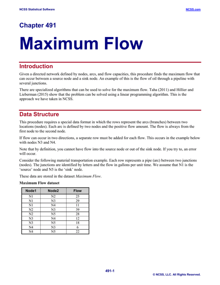
If flow can occur in two directions, a separate row must be added for each flow. This occurs in the example below
with nodes N3 and N4.
Note that by definition, you cannot have flow into the source node or out of the sink node. If you try to, an error
will occur.
Consider the following material transportation example. Each row represents a pipe (arc) between two junctions
(nodes). The junctions are identified by letters and the flow in gallons per unit time. We assume that N1 is the
‘source’ node and N5 is the ‘sink’ node.
These data are stored in the dataset Maximum Flow.
Maximum Flow dataset
Node1
Node2
Flow
N1
N1
N1
N2
N2
N3
N3
N4
N4
N2
N3
N4
N3
N5
N4
N5
N3
N5
25
29
11
39
28
12
18
6
22
491-1
© NCSS, LLC. All Rights Reserved.
NCSS Statistical Software
NCSS.com
Maximum Flow
Linear Programming Formulation of the Maximum Flow Problem
As stated earlier, we use a linear programming algorithm to solve for the maximum. Rather than present all the
equations, we show how the above example is translated into a linear programming tableau. The LP tableau for
the above data is
X12
Maximize
Nodes
N2
N3
N4
Capacities
(Bounds)
z=
1
X13
1
X14
1
29
X25
X34
X35
X43
X45
RHS
1
1
25
X23
1
11
-1
1
-1
39
28
-1
1
12
-1
18
1
-1
6
-1
22
=0
=0
=0
Procedure Options
This section describes the options available in this procedure.
Specifications Tab
Set the specifications for the analysis.
Starting and Ending Nodes of Each Arc
Node 1 (Starting) Column
Specify the column containing the starting node of each arc.
An arc connects two nodes. Each row specifies of a single, directed arc by giving its beginning node and ending
node as well as the flow capacity from start to end. Because the flow can only be in one direction, the order of the
arcs is critical. If flows in either direction are possible, a separate arc must be entered for each direction.
Each node may be specified by a number or a text value.
A directed arc is defined as a starting node followed by an ending node along with the flow capacity between
them. Other names for arcs are edges, lines, and links.
A source and sink node must be entered. The source node cannot have flow into it, thus the source node can only
occur in the Node 1 Column. A sink node cannot have flow leaving it.
Node 2 (Ending) Column
Specify the column containing the ending node of each arc.
A arc connects two nodes. Each row specifies of a single, directed arc by giving its starting node and ending node
as well as the flow capacity from start to end. Because the flow can only be in one direction, the order of the arcs
is critical. If flows in either direction are possible, a separate arc must be entered for each direction.
Each node may be specified by a number or a text value.
A directed arc is defined as a starting node followed by an ending node along with the flow capacity between
them. Other names for arcs are edges, lines, and links.
A source and sink node must be entered. The source node cannot have flow into it. A sink node cannot have flow
leaving it. Thus the sink node can only occur in the Node 2 Column.
491-2
© NCSS, LLC. All Rights Reserved.
NCSS Statistical Software
NCSS.com
Maximum Flow
Arc Capacities
Flow Capacity Column
Specify the column containing the arc's flow capacity. This is the upper maximum that can flow from node 1 to
node 2.
If flows can occur in both directions, a separate row must be entered for each flow.
The values must be positive numbers.
Source and Sink Nodes
Node Values Input Type
Specify how you will enter the node names of the source and sink nodes. The possible selections are
Use the first and last node names after sorting
The names of the nodes will be sorted and the first node name will be designated as the starting node value and te
last node name will be designated as the ending node value.
Enter custom source and sink values
Two text boxes will appear that will allow you to enter the names of the source and sink nodes.
Source (Starting) Node Value
Enter the value (number or text) of the source node. The procedure will find the maximum flow from this node to
the sink node.
Sink (Ending) Node Value
Enter the value (number or text) of the sink node. The procedure will find the maximum flow from the source
node to this node.
Reports Tab
Select Reports
Maximum Flow Solution, Possible Network Arcs
Indicate which reports you want to view.
Report Options
Column Names
This option lets you select whether to display only variable names, variable labels, or both.
491-3
© NCSS, LLC. All Rights Reserved.
NCSS Statistical Software
NCSS.com
Maximum Flow
Example 1 – Maximum Flow through a Pipeline
This section presents an example of how to find the maximal flow between nodes N1 and N5 in the following
network. As you use this example, you need to keep in mind that all flows are in only one direction.
Maximum Flow dataset
Node1
Node2
Flow
N1
N1
N1
N2
N2
N3
N3
N4
N4
N2
N3
N4
N3
N5
N4
N5
N3
N5
25
29
11
39
28
12
18
6
22
You may follow along here by making the appropriate entries or load the completed template Example 1 by
clicking on Open Example Template from the File menu of the Maximum Flow window.
1
Open the Max Flow dataset.
•
From the File menu of the NCSS Data window, select Open Example Data.
•
Click on the file Max Flow.NCSS.
•
Click Open.
2
Open the Maximum Flow window.
•
Using the Analysis menu or the Procedure Navigator, find and select the Maximum Flow procedure.
•
On the menus, select File, then New Template. This will fill the procedure with the default template.
3
Specify the problem.
•
On the Maximum Flow window, select the Specifications tab.
•
Double-click in the Node 1 (Starting) Column text box. This will bring up the column selection window.
•
Select Node1 from the list of columns and then click Ok. “Node1” will appear in this box.
•
Double-click in the Node 2 (Ending) Column text box. This will bring up the column selection window.
•
Select Node2 from the list of columns and then click Ok. “Node2” will appear in this box.
•
Double-click in the Flow Capacity Column text box. This will bring up the column selection window.
•
Select Flow from the list of columns and then click Ok. “Flow” will appear in this box.
•
Set the Node Value Input Type to Enter custom source and sink values.
•
Set Source (Starting) Node Value to N1.
•
Set Sink (Ending) Node Value to N5.
4
Run the procedure.
•
From the Run menu, select Run Procedure. Alternatively, just click the green Run button.
491-4
© NCSS, LLC. All Rights Reserved.
NCSS Statistical Software
NCSS.com
Maximum Flow
Maximum Flow Solution
Maximum Flow
Arc
(Row)
1
2
3
5
6
7
9
Maximum
Flow
Through
Arc
25
29
11
25
11
18
22
Total
65
Flow
(Capacity)
25
29
11
28
12
18
22
Node1
(Start)
N1 (Source)
N1 (Source)
N1 (Source)
N2
N3
N3
N4
Node2
(End)
N2
N3
N4
N5 (Sink)
N4
N5 (Sink)
N5 (Sink)
This report lists the solution by giving the arcs that form the maximal flow. The starting node is identified with
the word Source. The ending node is identified with the word Sink.
The maximum flow through the network is 65.
Possible Network Arcs
Possible Network Arcs
Arc
(Row)
1
2
3
4
5
6
7
8
9
Flow
(Capacity)
25*
29*
11*
39
28*
12*
18*
6
22*
Node1
(Start)
N1 (Source)
N1 (Source)
N1 (Source)
N2
N2
N3
N3
N4
N4
Node2
(End)
N2
N3
N4
N3
N5 (Sink)
N4
N5 (Sink)
N3
N5 (Sink)
* The starred links are part of the maximum flow.
This report lists all the arcs from which the maximal flow was derived. The starting node is identified with the
word Source. The ending node is identified with the word Sink.
491-5
© NCSS, LLC. All Rights Reserved.


