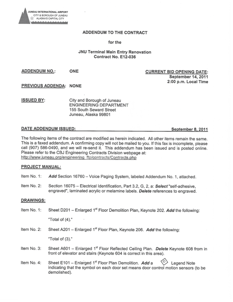
Addendum 1
advertisement

SECTION 16760 - VOICE PAGING SYSTEM PART 1 - GENERAL 1.1 RELATED DOCUMENTS A. 1.2 Drawings and general provisions of the contract, including General and Supplementary Conditions and Division 1 Specification sections, apply to this section. SUMMARY A. This section includes devices, wire, cable, connecting devices, installation, and testing for a complete and operational voice paging systems. B. Work Includes: 1. 2. 3. 1.3 Recessed ceiling speakers matching existing speakers in facility. Vandal Resistant outdoor speakers matching existing speakers in facility. Interface to existing speakers. DEFINITIONS A. EMI: Electromagnetic interference. B. PVC: Polyvinyl chloride. C. STP: Shielded twisted pair. D. UTP: Unshielded twisted pair. 1.4 SUBMITTALS A. Product Data: Include data on features, ratings, and performance for each component specified. For audio power amplifiers, indicate the NEC class of output wiring. B. Field quality-control test reports. 1.5 QUALITY ASSURANCE A. Electrical Components, Devices, and Accessories: Listed and labeled as defined in NFPA 70, Article 100, by a testing agency acceptable to authorities having jurisdiction, and marked for intended use. B. Comply with NFPA 70. ADDENDUM NO. 1 JNU TERMINAL MAIN ENTRYRENOVATION CBJ Contract No. E12-036 VOICE PAGING SYSTEM Page 16760-1 SECTION 16760 - VOICE PAGING SYSTEM PART 2 - PRODUCTS 2.1 FUNCTIONAL DESCRIPTION OF SYSTEM A. Reproduce high-quality sound that is free of noise and distortion at all speakers at all times during equipment operation. The system shall be free of noise during standby mode. B. Integrate with the present control system and functional scheme.. 2.2 MANUFACTURERS A. Manufacturers: Subject to compliance with requirements, provide products by the following: 1. 2.3 Valcom (Interior Model V-1020C and Exterior Model V-9010) SYSTEM COMPONENTS A. Self-Powered Loudspeakers for Indoor Locations 1. Performance: a. b. c. Sensitivity: 97 dB SPL @ 1 meter @ 1 watt. Frequency response: 200 to 8,000 Hz, +/-3dB. Distortion: < 1.5% @ 1 Watt RMS. 2. Electrical: 3. a. Tip-Ring input impedance: 600 ohm, nominal b. Power amplifier output: 1 Watt RMS c. Power Supply: -24V @ 50mA. Features: a. b. c. 4. Type: 8” dual cone. Integral volume control. Wide sound dispersion. Construction: a. b. Enclosures: Steel housing or back boxes, acoustically dampened, with front face of at least 0.0478-inch steel and whole assembly rust proofed and factory primed; complete with mounting assembly and suitable for flush wall, flush ceiling mounting; and with relief of back pressure. Baffle: For flush speakers, minimum thickness of 0.032-inch aluminum, with textured white finish. ADDENDUM NO. 1 JNU TERMINAL MAIN ENTRYRENOVATION CBJ Contract No. E12-036 VOICE PAGING SYSTEM Page 16760-2 SECTION 16760 - VOICE PAGING SYSTEM B. Self-Powered Loudspeakers for Outdoor Locations 1. Performance: a. b. c. 2. Electrical: a. b. c. 3. Vandal Resistant. Water Resistant. Tamper Resistant Screws Type: 8” dual cone. Wide sound dispersion. Construction: a. b. C. Tip-Ring input impedance: 600 ohm, nominal Power amplifier output: 1 Watt RMS Power Supply: -24V @ 50mA. Features: a. b. c. d. e. 4. Sensitivity: 97 dB SPL @ 1 meter @ 1 watt. Frequency response: 200 to 8,000 Hz, +/-3dB. Distortion: < 1.5% @ 1 Watt RMS. Enclosures: 18 guage steel with baked white powder coat urethane finish.. 24 gauge steel screen behind baffle to prevent sharp objects from penetrating speaker. Conductors and Cables: Jacketed, twisted pair and twisted multipair, untinned solid copper. Sizes as recommended by system manufacturer, but not smaller than No. 22 AWG. 1. 2. 3. 4. Insulation for Wire in Conduit: Thermoplastic, not less than 1/32 inch thick. Shielding: Foil, full copper braid, or both. Coverage shall exceed 95%. Plenum Cable: Listed and labeled for plenum installation. Provide ferrite bead on each circuit to speakers. PART 3 - EXECUTION 3.1 EXAMINATION A. Examine pathway elements intended for cables. Check raceways, cable trays, and other elements for compliance with space allocations, installation tolerances, hazards to cable installation, and other conditions affecting installation. Proceed with installation only after unsatisfactory conditions have been corrected. ADDENDUM NO. 1 JNU TERMINAL MAIN ENTRYRENOVATION CBJ Contract No. E12-036 VOICE PAGING SYSTEM Page 16760-3 SECTION 16760 - VOICE PAGING SYSTEM 3.2 INSTALLATION A. Wiring Method: Install wiring in raceways except in accessible ceiling spaces where cable wiring method may be used. Use plenum cable in environmental air spaces including plenum ceilings. Conceal cables and raceways except in unfinished spaces noted on the plans. B. Install exposed cables parallel and perpendicular to surfaces or exposed structural members, and follow surface contours. Secure and support cables by J-hooks, or similar fittings so fabricated and installed to avoid damage to cables. Secure cable at intervals not exceeding 30 inches and not more than 6 inches from cabinets, boxes, or fittings. C. Wiring within Enclosures: Bundle, lace, and train conductors to terminal points with no excess. Use lacing bars in cabinets. D. Control-Circuit Wiring: Install number and size of conductors as recommended by system manufacturer for control functions indicated. E. Separation of Wires: Separate line-level, speaker-level, and power wiring runs. Install in separate raceways or, where exposed or in same enclosure, separate conductors at least 12 inches for speaker and adjacent parallel power and telephone wiring. Separate other intercommunication equipment conductors as recommended by equipment manufacturer. F. Splices, Taps, and Terminations: Arrange on numbered terminal strips in junction, pull, and outlet boxes; terminal cabinets; and equipment enclosures. G. Match input and output impedances and signal levels at signal interfaces. Provide matching networks where required. H. Identification of Conductors and Cables: Color-code conductors and apply wire and cable marking tape to designate wires and cables so they identify media in coordination with system wiring diagrams. 3.3 Connect wiring according to Section 16120 - Conductors and Cables. 3.4 GROUNDING A. Comply with Section 16060 - Grounding and Bonding. B. Ground cable shields, drain conductors, and equipment to eliminate shock hazard and to minimize ground loops, common-mode returns, noise pickup, cross talk, and other interference. Provide ground reference isolation (audio transformers) between system components as necessary to break any remaining ground loops. C. Bond shields and drain conductors to ground at only one point in each circuit. ADDENDUM NO. 1 JNU TERMINAL MAIN ENTRYRENOVATION CBJ Contract No. E12-036 VOICE PAGING SYSTEM Page 16760-4 SECTION 16760 - VOICE PAGING SYSTEM 3.5 FIELD QUALITY CONTROL A. Perform the following field tests and inspections and prepare test reports: 1. 2. B. Operational Test: After installation of cables and speakers, demonstrate product capability and compliance with requirements. Test each signal path for end-to-end performance from each end of all pairs installed. Remove temporary connections when tests have been satisfactorily completed. Utilizing a Pink Noise Generator and Real-Time Spectrum Analyzer (RTA), confirm frequency response within plus or minus 3 dB from 70 to 15,000 Hz directly below each speaker. Adjust equalization on paging processor until above frequency response is realized. Remove malfunctioning units, replace with new units, and retest as specified above. END OF SECTION ADDENDUM NO. 1 JNU TERMINAL MAIN ENTRYRENOVATION CBJ Contract No. E12-036 VOICE PAGING SYSTEM Page 16760-5

