GE
Security
EST Fire & Life Safety
EST3 Multiplexed Fire Alarm System
Overview
Standard Features
The remote microphone panel is a supervised remote microphone,
used with the Audio Source Unit’s (3-ASU) remote microphone input.
The remote microphone panel is available in two packages. The
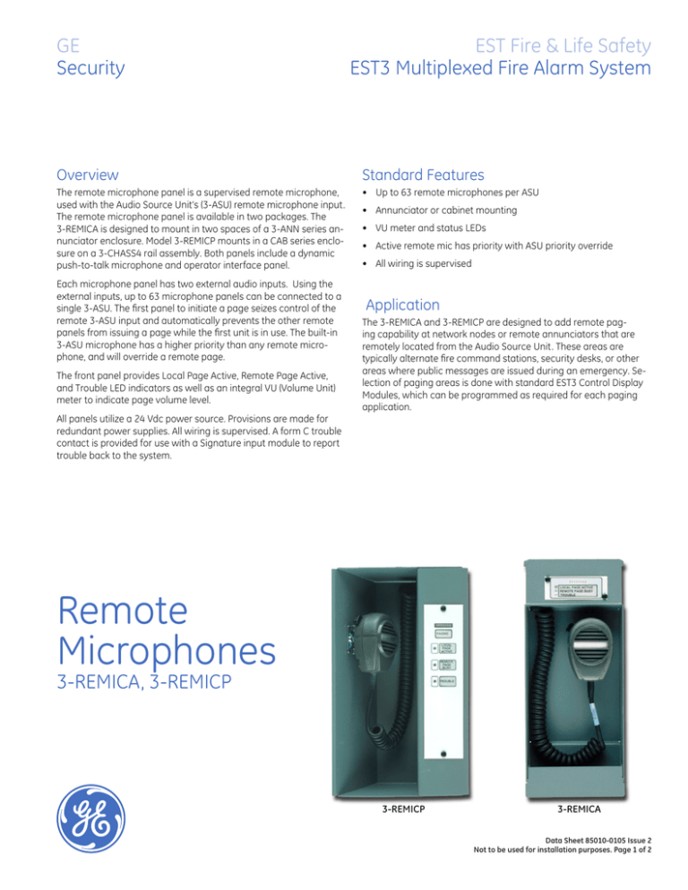
3‑REMICA is designed to mount in two spaces of a 3-ANN series annunciator enclosure. Model 3-REMICP mounts in a CAB series enclosure on a 3-CHASS4 rail assembly. Both panels include a dynamic
push-to-talk microphone and operator interface panel.
• Up to 63 remote microphones per ASU
Each microphone panel has two external audio inputs. Using the
external inputs, up to 63 microphone panels can be connected to a
single 3-ASU. The first panel to initiate a page seizes control of the
remote 3-ASU input and automatically prevents the other remote
panels from issuing a page while the first unit is in use. The built-in
3-ASU microphone has a higher priority than any remote microphone, and will override a remote page.
The front panel provides Local Page Active, Remote Page Active,
and Trouble LED indicators as well as an integral VU (Volume Unit)
meter to indicate page volume level.
• Annunciator or cabinet mounting
• VU meter and status LEDs
• Active remote mic has priority with ASU priority override
• All wiring is supervised
Application
The 3-REMICA and 3-REMICP are designed to add remote paging capability at network nodes or remote annunciators that are
remotely located from the Audio Source Unit. These areas are
typically alternate fire command stations, security desks, or other
areas where public messages are issued during an emergency. Selection of paging areas is done with standard EST3 Control Display
Modules, which can be programmed as required for each paging
application.
All panels utilize a 24 Vdc power source. Provisions are made for
redundant power supplies. All wiring is supervised. A form C trouble
contact is provided for use with a Signature input module to report
trouble back to the system.
Remote
Microphones
3-REMICA, 3-REMICP
3-REMICP
3-REMICA
Data Sheet 85010-0105 Issue 2
Not to be used for installation purposes. Page of 2
GE
Security
U.S.
T 888-378-2329
F 866-503-3996
Canada
T 519 376 2430
F 519 376 7258
Asia
T 852 2907 8108
F 852 2142 5063
Typical Wiring
To Audio Source Unit or
next Remote Microphone Unit
Latin America
T 305 593 4301
F 305 593 4300
www.gesecurity.com/est
© 2008 General Electric Company
All Rights Reserved
AUDIO IN
AUDIO OUT
KEY IN
From Remote Microphone
AUDIO IN
From secondary
24VDC riser
From Remote Microphone
KEY IN
NC
C
NO
From primary
24VDC riser
Australia
T 61 3 9259 4700
F 61 3 9259 4799
Europe
T 32 2 725 11 20
F 32 2 721 86 13
KEY OUT
TB1
1
2
3
4
5
6
7
8
9 10 11 12 13 14 15 16 17 18 19 20
To trouble relay
interface circuit
1.8 KOhm EOL if not connected
to another remote microphone
Engineering Specifications
Remote paging microphones shall be provided at the locations specified on the drawings.
Each remote microphone shall provide a dynamic Push-to-Talk microphone, Page level meter, Local Page Active LED, Remote Page Active LED, and Trouble LED. Selection of paging areas shall be provided using Control Display Modules, which can be programmed as required
for each paging application. The system shall support up to 63 remote microphones.
Technical Specifications
Installation
3-REMICA Takes up two spaces in the 3-ANN series of annunciator cabinets.
3-REMICP Remote microphone in chassis for use in CAB series cabinets.
Input Power
21 to 27 VDC Current: 64 mA
Microphone
Dynamic, PTT
Audio Output
1 VRMS into 1K Ohms
Audio Input
1 VRMS into 1K Ohms
Frequency Response
100 - 4,000 Hz
Supervision Audio Key (PTT)
1 KHz Tone Pulse DC for opens and shorts
Wiring
Maximum Resistance 210 ohms max. from output of last cascaded remote microphone to
3-ASU remote microphone input
Wire Type Audio = Twisted-shielded pair, 14 - 26 AWG
Key (PTT) = Twisted pair, 14 - 26 AWG
Page level meter, Local Page Active LED, Remote Page Active LED,
Indicators
Trouble LED
Agency Listings
UL, ULC
Operating Environment
32°F (0°C) to 120°F (49°C), 93% RH Non-condensing
Ordering Information
Catalog
Number
3-REMICA
3-REMICP
3-CHASS4
Description
Remote microphone for use in 3-ANN series annunciator cabinets
Remote microphone in chassis for use in CAB series cabinets
Chassis, with space for a 3-REMICP or 3-ASU and four local rail
modules, for use in CAB series cabinets
Ship Wt.
lb (kg)
15 (6.8)
15 (6.8)
8.5 (3.9)
Data Sheet 85010-0105 Issue 2
Not to be used for installation purposes. Page of 2


