BED X-TENDER™ Install Guide
advertisement

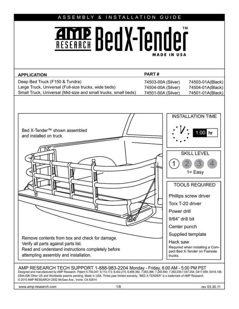
ASSEMBLY & INSTALLATION GUIDE APPLICATION PART # Deep Bed Truck (F150 & Tundra) Large Truck, Universal (Full-size trucks, wide beds) Small Truck, Universal (Mid-size and small trucks, small beds) 74503-00A (Silver) 74504-00A (Silver) 74501-00A (Silver) 74503-01A(Black) 74504-01A(Black) 74501-01A(Black) INSTALLATION TIME Bed X-Tender™ shown assembled and installed on truck. 1:00 hr SKILL LEVEL 1 2 3 4 1= Easy TOOLS REQUIRED Phillips screw driver Torx T-20 driver Power drill 9/64” drill bit Center punch Remove contents from box and check for damage. Verify all parts against parts list. Read and understand instructions completely before attempting assembly and installation. Supplied template Hack saw Required when installing a Compact Bed X-Tender on Flairside trucks. AMP RESEARCH TECH SUPPORT 1-888-983-2204 Monday - Friday, 6:00 AM - 5:00 PM PST Designed and manufactured by AMP Research. Patent 5,700,047; 6,113,173; 6,402,215; 6,806,392; 7,063,366; 7,240,940; 7,393,035;7,547,054; D417,859; D418,106; D544,826 Other US and Worldwide patents pending. Made in USA. Three-year limited warranty. “BED X-TENDER” is a trademark of AMP Research. © 2010 AMP RESEARCH 2552 McGaw Ave., Irvine, CA 92614 www.amp-research.com 1/8 rev 03.30.11 AMP RESEARCH BED X-TENDER™ PARTS LIST AND HARDWARE IDENTIFICATION 1 2 x2 3 x6 20-01998-90 Phillips head screw, self tapping 15-3709L-90 15-3709R-90 Quick Mount Bracket 6 4 x2 x4 Silver: 20-01743-90B (Large) Black: 20-01743-93B (Large) Silver: 20-01743-90A (Large) Black: 20-01743-93A (Large) Silver: 20-03023-90H (Deep) Black: 20-03023-91H (Deep) Silver: 20-03023-90 (Deep) Black: 20-03023-91 (Deep) Silver: 20-02237-90H (Small) Black: 20-02237-91H (Small) Silver: 20-02237-90 (Small) Black: 20-02237-91 (Small) Pre-drilled bent tube (center) Bent Tube x2 20-02293-13 (Large/ Deep) 20-02105-13 (Small) Pivot upright 7 x2 20-02668-11 (Large/ Deep) 20-02648-11 (Small) Center upright 5 x3 8 Silver: 20-02238-94 Black: 20-01663-94 Center tube 9 x18 11-02064-90 PT-Screw 14 x2 20-02293-12 (Large/ Deep) 20-02105-12 (Small) Bumper upright 10 x12 20-02065-90 Large wedge x2 11 x6 20-02650-90 Thru-hole wedge 12 x6 20-02649-90 Threaded double wedge www.amp-research.com x6 20-01696-90 Tube end cap 17 16 x2 x2 20-02110-90 20-02044-90 Strap latch assembly Phillips head screw Strap latch retainer 80-01671-93 (Large/Deep) 20-02504-94 (Small) 13 15 2/8 18 x2 x2 11-02162-90 11-02098-90 Strap latch insert Socket cap screw (Only Provided on (Only Provided on Deep Bed/Small Kits) Deep Bed/Small Kits) rev 03.30.11 AMP RESEARCH BED X-TENDER™ ADDITIONAL MOUNTING KITS DESCRIPTION No-Drill Mounting Bracket Kit – Ford F-Series APPLICATION PART # 2004+ F-150 2008+ F-250 2008+ F-350 10-74602-01A GM S-Series Mazda B-Series Nissan Pickup Toyota Pickup (Pre 2005 models) 10-74601-01A OPTIONAL L-Bracket Mounting Kit REQUIRED TO COMPLETE INSTALLATION www.amp-research.com 3/8 rev 03.30.11 AMP RESEARCH BED X-TENDER™ UNIVERSAL MOUNTING BRACKET INSTALLATION Cut out supplied template and tape to the D-pillar as shown. Using a center punch, mark holes as specified by the template. 1 x2 Quick Mount Bracket 2 x6 Phillips head screw 1 Using a power drill and 9/64” drill bit, drill through the sheet metal. If equipped with a bedliner, drill through bedliner. 2 Fasten mounting brackets using the supplied self-tapping Phillips screws and torque to 30 in. lbs. If equipped with a bedliner, install mounting brackets over bedliner. 1 2 NOTE: If bedliner has contours that may prohibit a flat, solid mounting surface, cut out a rectangular section to clear the bracket and mount the bracket directly to the metal D-pillar. 3 www.amp-research.com 4/8 rev 03.30.11 AMP RESEARCH BED X-TENDER™ BED X-TENDER ASSEMBLY Slide (3) bent tubes through pivot upright, bends facing up. Locate drilled tube in center position. Pivot should be on bottom. 3 4 Slide strap latch over outside tube with plastic insert facing up. (Passenger side shown, Driver side opposite.) Slide bumper upright over the (3) bent tubes. 15 8 6 14 1 Insert Phillips screw through pivot upright and predrilled center tube. Torque screw to 18 in. lbs. 2 Insert large wedge and PT screw into bumper upright and assemble loosely. The bumper upright will be adjusted and tightened later in Step 11 & 12. Place center upright over the (3) open tube ends as shown. 7 10 3 9 4 Place assembly on flat surface as shown. The tube ends should extend through the pivot upright approximately. 3/8” Secure pivot upright with large wedge and PT screw. Torque to 20 in. lbs. 16 Install strap latch retainers. Install end caps. 10 13 9 5 www.amp-research.com 6 5/8 rev 03.30.11 AMP RESEARCH BED X-TENDER™ BED X-TENDER ASSEMBLY – CONTINUED Slide (3) center tubes into the open ends of the bent tubes as shown. Connect the two halves. Make sure there is at least 3” overlap with the bent tubes on each side. 5 *For flareside trucks using compact Bed X-Tender cut 4” off of each half of bent tubes. 7 8 Adjust the width of the Bed X-Tender by placing the pivots into the mounting brackets. Secure the center uprights with double wedges and PT screws. (The thru-hole wedge is placed in the shallow pocket.) 12 9 9 11 10 Adjust bumper uprights so that the rubber bumper rests on a flat surface on the tailgate. * Rotate Bed X-Tender into the bed and check that the rubber bumper position is on a flat surface. Torque PT screws to 20 in. lbs. Close tailgate and check for clearance. * *If bumper uprights are at the edge of the tailgate, position them along the radius. 11 www.amp-research.com 12 6/8 When Bed X-Tender is out on the tailgate be sure to fasten strap latches properly. Note: For tailgates with side latches, nylon inserts must be removed from buckles. rev 03.30.11 A MAPMRP ERSEES A D XX- -TTE E E ARRCCHH BB E ED NN DD E RE™R ™ For Toyota applications the supplied strap latch insert must be used. Install 1 piece insert with the provided 10/32 x 7mm socket head cap screw with a 4mm hex key. Repeat for other strap. Remove the PT screw with a T20 Torx driver. 18 17 13 14 When the Bed Extender is at the furthest rear position, push down on the buckle to insert into tailgate latch. Tighten straps. To release, pull tailgate handle. NOTE: Ensure that buckles are properly inserted into latches by pulling on the straps after both buckles have been inserted. 1 15 www.amp-research.com 7/8 rev 03.30.11 L I M IT E D WARRANTY AMP RESEARCH warrants product to be free from defects in material and workmanship, for terms specified below, provided there has been normal use and proper maintenance. This warranty applies to the original purchaser only. All remedies under this warranty are limited to the repair of replacement of any item found by the factory to be defective within the time period specified. If you have a warranty claim, first you must call our factory at the number below for instructions. You must retain proof of purchase and submit a copy with any items returned for warranty work. Upon completion of warranty work, if any, we will return the repaired or replaced item or items to you freight prepaid. Damage to our products caused by accidents, fire, vandalism, negligence, misinstallation, misuse, Acts of God, or by defective parts not manufactured by us, is not covered under this warranty. THE WARRANTY TIME PERIOD IS AS FOLLOWS: THREE YEARS FROM DATE OF PURCHASE. ANY IMPLIED WARRANTIES OF MERCHANTABILITY AND/OR FITNESS FOR A PARTICULAR PURPOSE CREATED HEREBY ARE LIMITED IN DURATION TO THE SAME DURATION AND SCOPE AS THE EXPRESS WRITTEN WARRANTY. OUT COMPANY SHALL NOT BE LIABLE FOR ANY INCIDENTAL OR CONSEQUENTIAL DAMAGE. Some states do not allow limitations on how long an implied warranty lasts, or the exclusion or limitation of incidental or consequential damages, so the above limitations or exclusions may not apply to you. This warranty gives you specific legal rights, and you may also have other rights that vary from state to state. FOR WARRANTY ISSUES WITH THIS PRODUCT PLEASE CALL AMP RESEARCH CUSTOMER SERVICE BY CALLING TOLL - FREE 1-888-983-2204 WAR N I N G The manufacturer strongly recommends that this product be professionally installed. Failure to carefully follow the electrical installation steps could result in severe electrical shock that could harm the installer and/or damage the vehicle. This product is designed to enhance the appearance of the vehicle. Do not rely in any way on the components of this product to contain occupants within the vehicle, or to protect against injury of death in the event of an accident. Never operate vehicle in excess of manufacturer’s specifications. WEAR SEAT BELTS AT ALL TIMES Read and follow, precisely, all installation instructions provided when installing this product. Failure to do so could place occupants of the vehicle in a potentially dangerous situation. After installing or reinstalling, check to make sure it has been properly installed. www.amp-research.com 8/8 rev 03.30.11 FACING REAR SIDE FOR LEFT BRACKET INSTALLATION Use dashed line for trucks with bedliners. FACING REAR SIDE FOR LEFT BRACKET INSTALLATION 1.81” TRUCK BED Use dashed line for trucks with bedliners. FACING REAR SIDE FOR RIGHT BRACKET INSTALLATION Cut or fold along solid lines. (Dashed lines for trucks with bedliners.) 8” Drill template for Bed X-Tender™ mounting brackets 1.3” 1.56” Use dashed line for trucks with bedliners. TRUCK BED Use dashed line for trucks with bedliners. FACING REAR SIDE FOR RIGHT BRACKET INSTALLATION 1.28” Drill template for Bed X-Tender™ mounting brackets NOTE: FOR TRUCKS WITH BEDLINERS, USE THIS TEMPLATE ON TOP OF BEDLINER. DO NOT CUT BEDLINER! 1.28” 1.81” 1.3” 1.56” 6.7”


