APS00B - Honeywell Sensing and Control
advertisement

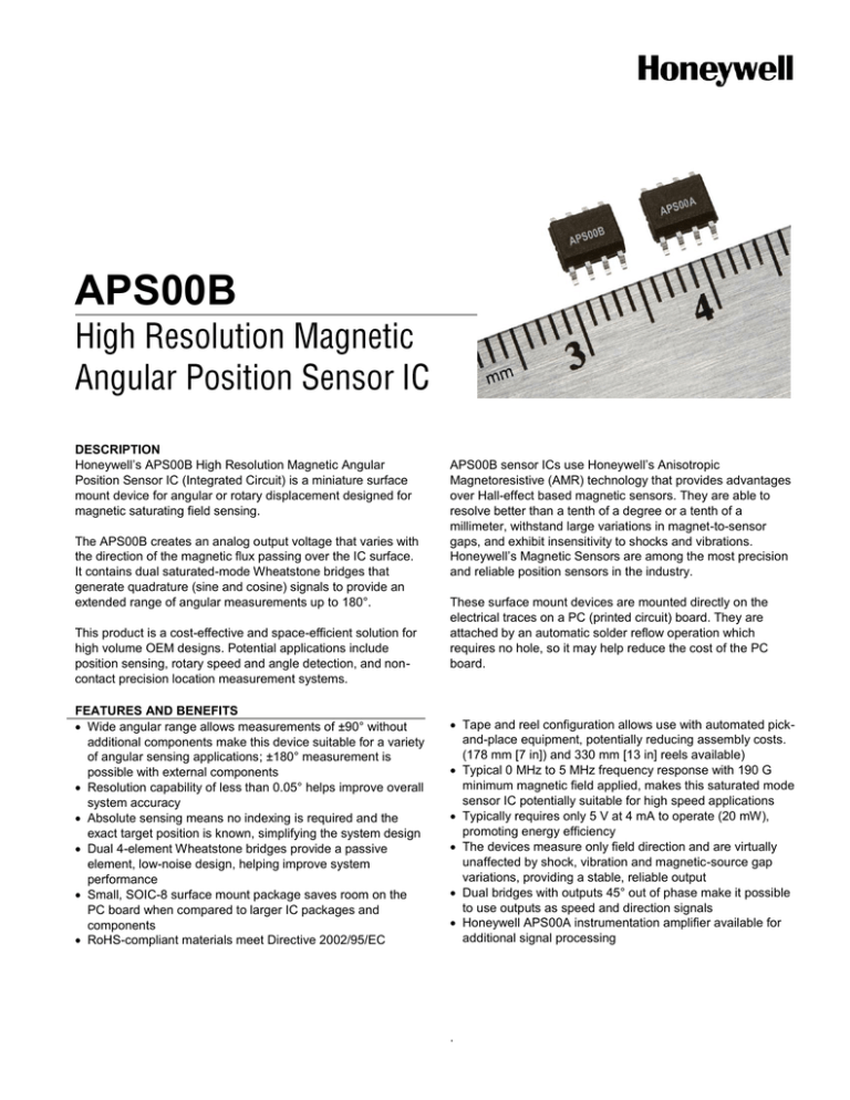
APS00B DESCRIPTION Honeywell’s APS00B High Resolution Magnetic Angular Position Sensor IC (Integrated Circuit) is a miniature surface mount device for angular or rotary displacement designed for magnetic saturating field sensing. The APS00B creates an analog output voltage that varies with the direction of the magnetic flux passing over the IC surface. It contains dual saturated-mode Wheatstone bridges that generate quadrature (sine and cosine) signals to provide an extended range of angular measurements up to 180°. This product is a cost-effective and space-efficient solution for high volume OEM designs. Potential applications include position sensing, rotary speed and angle detection, and noncontact precision location measurement systems. FEATURES AND BENEFITS Wide angular range allows measurements of ±90° without additional components make this device suitable for a variety of angular sensing applications; ±180° measurement is possible with external components Resolution capability of less than 0.05° helps improve overall system accuracy Absolute sensing means no indexing is required and the exact target position is known, simplifying the system design Dual 4-element Wheatstone bridges provide a passive element, low-noise design, helping improve system performance Small, SOIC-8 surface mount package saves room on the PC board when compared to larger IC packages and components RoHS-compliant materials meet Directive 2002/95/EC APS00B sensor ICs use Honeywell’s Anisotropic Magnetoresistive (AMR) technology that provides advantages over Hall-effect based magnetic sensors. They are able to resolve better than a tenth of a degree or a tenth of a millimeter, withstand large variations in magnet-to-sensor gaps, and exhibit insensitivity to shocks and vibrations. Honeywell’s Magnetic Sensors are among the most precision and reliable position sensors in the industry. These surface mount devices are mounted directly on the electrical traces on a PC (printed circuit) board. They are attached by an automatic solder reflow operation which requires no hole, so it may help reduce the cost of the PC board. Tape and reel configuration allows use with automated pickand-place equipment, potentially reducing assembly costs. (178 mm [7 in]) and 330 mm [13 in] reels available) Typical 0 MHz to 5 MHz frequency response with 190 G minimum magnetic field applied, makes this saturated mode sensor IC potentially suitable for high speed applications Typically requires only 5 V at 4 mA to operate (20 mW), promoting energy efficiency The devices measure only field direction and are virtually unaffected by shock, vibration and magnetic-source gap variations, providing a stable, reliable output Dual bridges with outputs 45° out of phase make it possible to use outputs as speed and direction signals Honeywell APS00A instrumentation amplifier available for additional signal processing . APS00B POTENTIAL APPLICATIONS Transportation: High accuracy angular position sensing Rotary speed and angle detection Non-contact precision displacement sensing Speed and direction sensing Industrial: High accuracy angular position sensing Rotary speed and angle detection Non-contact precision displacement sensing Valve position Robotics control Medical: High accuracy angular position sensing Rotary speed and angle detection Non-contact precision displacement sensing Table 1. Absolute Maximum Ratings* Parameter Supply voltage Power Dissipation Operating Temperature Magnetic flux Min. -12 – -55 [-67] – Max. +12 200 150 [302] no limit Unit V mW °C [°F] Gauss *Absolute maximum ratings are the extreme limits the device will withstand without damage to the device. However, the electrical and mechanical characteristics are not guaranteed as the maximum limits (above recommended operating conditions) are approached, nor will the device necessarily operate at absolute maximum ratings. Table 2. Characteristics (At Vs = 5.0 V and Ta = 25 °C [77 °F] unless otherwise noted.) Parameter Condition Typ. Max. Unit Supply voltage – – 5 12 V Operatingt Temperature – -40 [-40] – 150 [302] °C [°F] bridges are connected in parallel 0.9 1.25 1.6 kOhm – 4.0 7.0 mA around zero crossing – 2.1 2.3 mV/° Bridge resistance Supply current Sensitivity B > saturation field -90 – +90 ° Resolution – – 0.05 – ° Max. output amplitude – 47.5 57.5 67.5 mV Min. output amplitude – -47.5 -57.5 -67.5 mV Output amplitude (peak to peak) – 95 115 135 mV Offset voltage – -1 – 1 mV Amplitude change at 140°C [284°F] -34 – -43 % Amplitude change at -40°C [-40 °F] 24 – 31 % – -2 – 2 mV (Amp A/Amp B) * 100 97 – 103 % – -1 – 1 % <10 μV/Gauss amplitude change 60 190 – Gauss Angle range Offset shift Synchronism Synchronism shift Saturation level Bandwidth 2 Min. www.honeywell.com/sensing – 0 to 5.0 MHz Figure 1. Detection of Relative Motion of a Magnet in Angular Displacement The APS00B sensor can used to detect the relative motion of a magnet in angular displacement. Given a typical supply voltage of 5 V, each bridge will provide about 115 mV of swing (±57.5 mV) on top of 2.5 V bias voltage. With +5 V applied to it, the bridge performs a rail splitter function to create two near +2.5 V sources driven apart by V as created by the magnetic field and the offset error voltage. The bridge differential output voltages (V) for the APS00B are: VA = Vs S sin (2 θ) and VB = Vs S cos (2 θ) where: Vs = Supply Voltage (V) S = Material Constant = (R/Rmax) *(1/2) = 11.5 mV/V nominal θ = Reference to Magnetic Field Angle (°) Please refer to Application Sheet “How to Apply Honeywell APS00B Angular Position Sensors ICs” for additional details. Figure 2. Electrical Diagram Figure 3. Pinout and Sensing Element Location The APS00B has two sensor bridges optimized for rotary sensing applications. Thus the die is centered in all three dimensions within the SOIC-8 package. The figure below indicates the pin identification and the sensing element location. Bridge “A” output: VoutA = Vs*S*sin(2θ) + VosA, Bridge “B” output: VoutB = Vs*S*cos(2θ) + VosB where: S = 11.5 mV/V nominal VosA = Bridge A Offset (nominal = 0 V) where: S = 11.5 mV/G nominal VosB = Bridge B Offset (nominal = 0 V) Bridge A is centroidally co-located with Bridge B, and Bridge A elements are rotated by 45° relative to Bridge B elements as shown. Figure 4. Typical Bridge Outputs vs Rotation Angle Honeywell Sensing and Control 3 APS00B Figure 5. Common Wiring Diagrams Figure 6. Typical Wiring Diagram with Honeywell APS00A Instrumentation Amplifier 4 www.honeywell.com/sensing Figure 7. Mounting Dimensions (All dimensions for reference only: mm/[in].) SOIC-8 Package Tape Standard Reel (178 mm [7 in]) Large Reel (330 mm [13 in]) APS00M Magnet 23,5 Dia. [0.93] Magnetization Direction 11,0 [0.43] 3,35 [0.13] Honeywell Sensing and Control 5 Order Guide Catalog Listing APS00B APS00B-T13 APS00A APS00M Description High resolution magnetic angular position sensor IC, SOIC-8 surface-mount package, on tape and reel, 1,000 pieces on standard reel (178 mm [7 in]) High resolution magnetic angular position sensor IC, SOIC-8 surface-mount package, on tape and reel, 4,000 pieces on large reel (330 mm [13 in]) Instrumentation amplifier for APS00B, SOIC-8 surface-mount package, on tape and reel, 1,000 pieces on standard reel (178 mm [7 in]) Special magnet for APS00B WARNING WARNING PERSONAL INJURY DO NOT USE these products as safety or emergency stop devices or in any other application where failure of the product could result in personal injury. Failure to comply with these instructions could result in death or serious injury. WARRANTY/REMEDY Honeywell warrants goods of its manufacture as being free of defective materials and faulty workmanship. Honeywell’s standard product warranty applies unless agreed to otherwise by Honeywell in writing; please refer to your order acknowledgement or consult your local sales office for specific warranty details. If warranted goods are returned to Honeywell during the period of coverage, Honeywell will repair or replace, at its option, without charge those items it finds defective. The foregoing is buyer’s sole remedy and is in lieu of all other warranties, expressed or implied, including those of merchantability and fitness for a particular purpose. In no event shall Honeywell be liable for consequential, special, or indirect damages. While we provide application assistance personally, through our literature and the Honeywell web site, it is up to the customer to determine the suitability of the product in the application. Specifications may change without notice. The information we supply is believed to be accurate and reliable as of this printing. However, we assume no responsibility for its use. MISUSE OF DOCUMENTATION The information presented in this product sheet is for reference only. DO NOT USE this document as a product installation guide. Complete installation, operation, and maintenance information is provided in the instructions supplied with each product. Failure to comply with these instructions could result in death or serious injury. SALES AND SERVICE Honeywell serves its customers through a worldwide network of sales offices, representatives and distributors. For application assistance, current specifications, pricing or name of the nearest Authorized Distributor, contact your local sales office or: E-mail: info.sc@honeywell.com Internet: www.honeywell.com/sensing Phone and Fax: Asia Pacific +65 6355-2828 +65 6445-3033 Fax Europe +44 (0) 1698 481481 +44 (0) 1698 481676 Fax Latin America +1-305-805-8188 +1-305-883-8257 Fax USA/Canada +1-800-537-6945 +1-815-235-6847 +1-815-235-6545 Fax Sensing and Control Honeywell 1985 Douglas Drive North Golden Valley, MN 55422 www.honeywell.com/sensing 005924-2-EN IL50 GLO Printed in USA August 2011 © 2011 Honeywell International Inc. All rights reserved.


