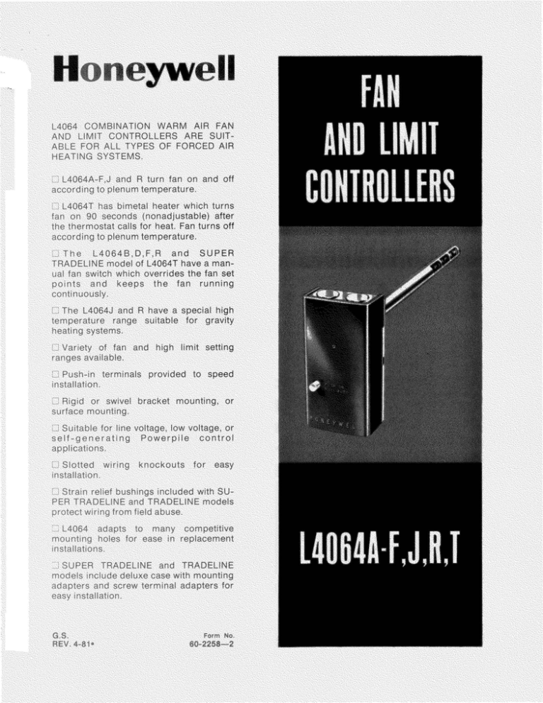
Product Data and Specifications-Product Data for
advertisement

SPECIFICATIONS
with
space for related controls.
TRADELINE
features as
8-32
below.
TRADELIN E MODELS A VA ILABLE:
L4064B Fan and Limit Controller.
TRADELINE FEATURES INCLUDE:
in
HIGH LIMIT
RANGE FACTORY·
SET
00
250
to
ORDERING INFORMATION
YOUR TRADELINE
FOR
WHEN PURCHASING
WHOLESALER OR YOUR
COMPLETE ORDERING
desired .
IF YOU HAVE ADDITIONAL
PRODUCTS OR SERVICES, PLEASE
1. YOUR LOCAL HONEYWELL RESIDENTIAL
DIRECTORY).
LIKE TO COMMENT ON
SALES OFFICE (CHECK WHITE PAGES
PHONE
GROUP CUSTOMER SERVICE
HON EYWELL
DOUGLAS DRIVE
MINNEAPOLIS, MINNESOTA 55422 (61 2)
{IN
P
CANADA- HONEYWELL
INTERNATIONAL
ELLESMERE ROAD,
ONTARIO
ALL PRI NCIPAL CITIES OF THE WORLD.
TABLE II - L4064 SPECIFICATIONS IN DEGREES CELSIUS.
HIGH LI MIT
FAN ·OFF
FAN ·ON
MANUAL
SCAL E
FACTORY·
FACTORY ·
FACTORY·
RANGE
RANGE
FA N SWITCH RANG E RANGE
SET
SET
SET
Helical bimetal
No
I
Yes
10
10
18
38
No
Fl at, spiral bimetal
121
52
to
to
to
to
38
Yes
21
93
121
102
No
Yes
'
Helical bimetal
27 to
66 to
No
27 to
38 to
143
177
Yes
177
152
None - fan
10
No
10
38
c'Omes on 90 sec.
to
to
to
Yes
121
after cal l for heat
93
1 21
SENSI NG ELEMEN T
MOD EL
L4064 A
L4064B
L4064C
L4064D
L4064 E
L4064 F
L4064J
L4064R
Standard L4064T
SUP ER TRADE LINE
L4064T
ELECTRICAL RA TINGS {amperes):
120 Vac
240 Vac
HIGH LIMIT DIFFERENTIAL: 25 F [14 CJ.
LIMIT STOP SETTING: 150 F to 250 F [66 C to 121 CJ
in 10 F [5 .6 CJ increments (specify when ordering ).
MINIM UM SWITCH TE MPERATU RE:
L4064A, T -minus 40 F [m inus 40 C] .
L4064B- F,J,R-plus 32 F [O CJ.
MAXIMUM SWITCH TEMPERATUR E: 190 F [88 CJ.
MAXIMUM ELEMENT TEMP ERATURE:
L4064 A-F,T-350 F [177 CJ.
L4064J, R-600 F [31 6 CJ .
MOUNTI NG DIMEN SIONS: See Fig. 1.
24 Vac
FAN - IM IT FAN LIMIT FA N LIM IT TIMER
Full
Load
Locked
84
Rotor
Max .
Amp
-
-
-
24
-1
-
-
-
-
2
.2
8
7
4
48
42
-
-
14
Pilot Duty-2 A at 25 Vac; 0.25 A at 0.25 to 12 Vdc.
Maximum Com b ined Connected Load-2000 VA.
r--2~ [60.4]-j
!
-----··rI
'
'
1--- H
I
(486]--1
I 1-fs1s.o1
i IT· --------+.t.,
; I
'
. I
-<H>
I
129250A DOUBLE WING BRACKET
1.(7.21
32
-I
1
(25.41
.!
------ ,
2
11~hs1
EL EMENT
2~
f;;
9
J"
TH IS CUTOUT DOWN
I
3i4 ( 19.1 (
5 J2
OUTER CASE.
DIM FOR
1134.21
~~ts~E6-~~~
[57.21
·········i· .. ·-
1ss11•1--J-L .tf2
0, ·
(5.6){4(
T
'---
--+---T
32642A SWIVEL BRACKET
1
I
,
i
-11..-I f
I I 19. tj
"""-- ~ ---r-- - -- -J
J - ,}13811-!
.
3 [76.21
I
I
NOTE: OVERALL DEPTH IS 2 IN CHES fS0,8 mm! ON ALL MODELS,
~DIA.
•
( 19.11 (2)
[6 .351
110265A SINGLE WING BRACKET
FIG. 1-MOUNTING DIMENSIONS IN in. [mm IN BRACKETS].
3
60-2258-2
MOUNTING MEANS:
L4064A,B,E,F,J,R,T-rigid bracket, swivel bracket,
or flush mounting.
L4064C,D-flush mounting only.
CASE DIMENSIONS: See Fig. 1.
WI RING KNOCKOUTS:
L4064A-F ,J,R-two in bottom of case, slotted for
easy installation.
L4064T -has one knockout in bottom of case.
UN DERWRITERS LABORATORIES INC. APPROVALS:
L4064A ,B,C,D,T LISTED-File MP466, Guide MBPR;
L4064E ,F,J and R COMPONENT REC OGNIZED- File MP466, Guide MBPR2.
ACCESSORIES:
1. 110265A Rigid Bracket-single wing, with No.
8-32 setscrew.
2. 129250A Rigid Bracket-double wing, with No.
8-32 setscrew.
3. 326 12A Swivel Bracket.
4. 137813 Strain Rel ief Bushing.
ELEM ENT DIMENSIONS:
L4064A,B,E,F,J,R,T (helical)-3/4 in. [1 9.1 mm]
diameter; 5, 8, or 11-1/2 in. [127, 203. 2 or 292.1
mm] insertion.
L4064C ,D (flat spiral)-1-1/2 in . (38 .1 mm]
diameter; 1-1 /2 in. [38.1 mm] insertion.
ADJ USTME NT MEAN S: Ad just able levers on
scaleplate .
FINISH : Zinc-plated steel.
[
I
FLUSH MOUNTING
WHEN INSTALLING THIS PRODUCT ...
1. Read these instructions carefully. Failure to follow
them could damage the product or cause a hazardous
condi tion.
2. Check the ratings given in the instructions and on
the product to make sure the product is suitable for
your application.
3. Installer must be a trained , experienced service
techn ician.
4. After installation is complete, check out product
operation as provided in these instructions.
L4064A,B,E,F,J,R,T
Hole in plenum should be just large enough to
accommodate the 3/4 in. (19.1 mm) diameter element
tube. For adequate clearance an 0.80 in. (20.3 mm]
diameter hole is recommended .
L4064C,D
Hole in plenum should be 1-9/16 in. [39.7 mm]
diameter to accommodate the 1-1 /2 in. [38.1 mm]
di ameter ele ment.
1. Remove cover by squeezing sides and pulling off.
Insert element in plenum and mark location of mounting holes. Make sure the case is snug against the
plenum before marking the mounting holes.
2. Punch or drill holes for mounting screws.
3. Place insulation between plenum and case if
necessary.
4. Fasten controller securely with mounting screws.
CAUTION
1. Disconnect power supply before beginning installation to prevent electrical shock and
equipment damage.
2. When connecting cable or conduit to control,
avoid straining the control case.
Follow furnace or burner manufacturer's instructions, if available. Do NOT exceed the ratings and
limitations given in this section.
FURNACE
PLENUM
LOCATION
If this is a replacement installation, locate the L4064
in the same location as the control being replaced.
Sensing tube length should be same as old control. If
this is a new installation, the element should be installed
only by a trained, experienced service technician according to the furnace manufacturer's instructions. The
element must not touch any internal part of the furn ace.
NOTE: The electrical rating is at maximum switch
tem perature of 190 F (88 CJ. If plenu m surface
tem peratu re exceeds 190 F (88 CJ. heat insulating
material or mounting bracket must be used. The
L4064J,R requires the use of a bracket in gravity
sytems.
HEAT
INSULA T ING
fl/.ATER lAL IF
NEED ED
MOUNTING
The devices may be mounted as follows:
L4064A,B,E,F,J.R,T-flush mounting or bracket (r ig id or swivel).
L4064C, D-flush mounting only.
FIG. 2-FLUSH MOUNTING (L4064A,B,E,F,J,R,T). REQUIRES A HOLE 0.80 in. [20.3 mm] DIAMETER
IN THE PLENUM.
4
STEEL BUSHING ADAPTER
(SUPER TRADELINE and TRADELINE models)
SWIVEL MOUNTING
L4064A,B,E,F,J,R.T may be swivel mou nted. The
swivel bracket requires a 1-9/16 in. [39.7 mm] hole in
the plenum (Fig. 3).
1. Use bracket as a template to make the location of
mounting holes in plenum. Drill or punch holes for
mounting screws.
2. Fasten the bracket in place with furnished screws.
Start the screws but do not tighten.
3. Insert element tube through bracket, straighten
controller, and fasten. Tighten the mounting screws
securely. It may be necessary to rotate the bracket to
tighten all screws securely.
1. Insert one-half of the split steel bushing through the
wire ring (Fig. 5). It may be necessary to spread the ring
slightly.
2. Insert the other half of the steel bushing into the
ring making sure tabs and ears are at the same ends.
3. Place bushing assembly on element, ear end first.
4. Holding bushing at seams, push firmly to the
control end of element.
5. Insert element tube with adapter through bracket,
straighten controller and fasten. Tighten setscrew. Be
sure screw strikes bushing and not inner sensing
element.
~FURNACE PLENUM
32612A SWIVEL
BRACKET
\
REQUIRE 1·9/16 in.
(40 mm] DIAMETER
HOLE IN PLENUM
FIG. 4-RIGID BRACKET MOUNTING REQUIRES A
HOLE 0.80 in. [20.3 mm] DIAMETER FOR
MOUNTING.
FIG. 3-SWIVEL MOUNTING. REQUIRES A 1-9/16
in. [39. 7 mm] DIAMETER MOUNTING HOLE
FOR ELEMENT INSERTION.
RIGID BRACKET MOUNTING
L4064
HELICAL ELEMENT
When mounting control on bracket, make sure
setscrew strikes tube frame and not inner sensing element.
2196A
FIG. 5- USING TRADELINE ADAPTER.
L4064A,B,E,F,J,R.T may be mounted usi ng a rigid
bracket. The rigid bracket requires a hole 0.80 in. [20.3
mm] diameter for mounting (Fig. 4).
1. Use bracket as a template to mark the location of
mounting holes in plenum. Drill or punch holes for
mou nting screws.
2. Fasten bracket in place with furnished screws.
Tighten the screws securely.
3. Insert element tube through bracket, straighten
controller and fasten by tightening setscrew. Be sure
screw strikes tube frame and does not strike inner
sensing element.
4. For replacement installations with existing 1 in.
[25.4 mm] diameter hole. SUPER TRAOELINE and
TRADELINE models are supplied with split steel
bushings and wire snap ring. Follow the instructions
below for using the steel bushing adapter.
WIRING
Disconnect power supply before beginning installation to prevent electrical shock and equipment damage.
All wiring mu st com ply with local electrical cod es
and ordinances or in the absence of local codes with
the National Electrical Code ANSI C1 - 1981-NFPA 70.
Follow burner or furnace manufacturer's instructions
if available; otherwise, proceed as follows.
--~~~~~-IMPORTANT~~~~~~...,
The metal-fiberboard jumper must be removed
when the limit is used in the low voltage circuit. To
remove, pull out. To replace, push metal
fiberboard jumper in with tab side up.
5
60-2258-2
INSTALLATION (SUPER
TRAD ELINE/TRADELINE shown)
The slotted knock outs on the bottom of the case and
the strain relief bushing are provided to simplify the
installation procedure and to protect the wires.
1. To remove the slotted knockout(s), use a longnose pliers as shown in Fig . 6 and pull straight down .
FIG. 8-CLOSING THE STRAIN RELIEF BUSHING.
When connecting cable or conduit to this control,
use care to avoid strain on the control case . When
connecting wires to the push -in terminals, use the
fol lowi ng procedure :
1. No. 14, 16, or 18 solid or No. 14 or 16 stranded
wire may be connected to the terminals.
2. Strip insulation from wires the distance shown by
the strip gauge on the controller.
3. Solid wire may be inserted by pushing into the
termi nal holes. If stranded wir e is used, insert a small
screwdriver into the slot next to the terminal (Fig. 9).
Push in and hold while inserting wire in terminal. Then
remove screwdriver. Stranded wire may be pushed
directly in if solder dipped .
~~~~~~~IMPORTA N T~~~~~~......
All wires mu st be clear of rotating scaleplate.
FIG. 6-REMOVING SLOTTED KNOCKOUTS.
2. Insert the strai n relief bush ing into the knockout
as shown. The open side of the b ushi ng should face the
open side of the knockout.
FAN OFF
INDICATOR
FAN ON
INDI C ATOR
1
\
....,,,'
t;:::::;:···
v····
~j
FIG. 7-INSERT STRAIN RELIEF BUSHING.
~--·:.~NT!C :i"/•_ Ti;-:{ WlHFS 1'0 TEM PE F-lATUHE
\(O NTHOL C!HUJIT L4064T ONLY
"
FIG. 9-INTERNAL VIEW OF L4064, SHOWING USE
OF SCREWDRIVER TO CONNECT OR DISCONNECT WIRES AT PUSH-IN TER MINALS.
NOTE: BECAUSE THE DIAL TURNS WHEN
THE ELEMENT TEMPERATURE CHANGES,
THE LETTERING ON THE DIAL MAY NOT
BE HORIZONTAL
3. Connect wire to the push-in terminals, pull wires
throug h slot. and lay side by side .
4. When the wires have been connected to the
control, close the movable gate on the strain relief
bushing. Use a channel lock pliers to snap the gate shut
{Fig. 8).
6
switch when it is desirable to connect more than one
wire to a te rmi nal.
SCREW TERMINAL ADAPTERS
(SU PER TRADEU NE and
TRADELINE models only)
NOTE: Because of temperature limitations on field
wiring, the screw adapters should be used ONLY
when the L4064 is installed on a mounting bracket.
Do not remove fiberboard insulator from upper
adapter; thi s insulates the adapter from the dial.
Two 123198A Screw Terminal Adapters are provided with SUPER TRADELINE and TRADELINE models for converting push-in terminals to screw type
termi nal s. These are for use on the fan si de of the
To install, push long, serrated prong all the way into
the round terminal hole so that tip of small prong fits
into square hole (Fig. 10).
TERMINAL
SC REW
L4064T
FA N
SI DE
-FISER80A R D
INSULATO R
LIMIT
SIDE
FAN
MOTOR
18 in, [457.2 mm }
LEADWIRES
LI
{Hr
L1
&
&
B.
A.INS ERTING SCREW TERMINAL ADAPTERS WITH FIBERBOARD INSULATOR.
11
r
POWER S UPPLY. PROVIDE DISCO NN ECT MEANS AND OV ERLOAD
PROTECT ION AS REQUIRED.
ADD 0.10 AMP TO ANTICIPATOR SETTING ON THERMOSTAT .
TO USE AS LOW VOLTAGE LIMIT REMOVE JUMPER.
8. FIBERBOARD INSULATOR CORRECTLY FOLDE D FOR USE WITH UPPER
TERMINAL HOLE.
C. FIBERBOA RD INSULATOR CORRECTLY FOLDE D FOR USE WITH LO WER
TE RMINA L HOLE .
FIG. 10-INSTALLING SCREW TERMINAL ADAPTER.
A
FIG . 12-L4064T 3-WIRE LINE VOLTAGE HOOKUP.
c
B
L4064
L4064
L4064
~~~~v~ o----
UMlT
JUMPE.R
<;1DE
REMOVED
I
j,/~P-lOT)
i
J
-+- Ll-t-- ---..__,
~~~PEL~
i .._ 1
. 2---------
I
&
i~\
--'
ADO DISCONNECT ME.ANS ANO OVERLOAD PRO"TECTION
AS R EQUfREO ,
TO CON Tn Ot.l.f:'D L.OW VO L T AG E EQU1PMf:NT
;3\ TO CON T Hou.E D LINE
VOLT A GE'. E.QUtPMENT
FIG. 11 - A: LIMIT IN LOW VOLTAGE CIRCUIT.
B: LIMIT IN LINE VOLTAGE CIRCUIT.
C: LIMIT IN LI NE VOLTAGE CIRCUIT WITHOUT JUMPER.
7
60-2258-2
CAUTION
When adjusting the fa n and limit setting levers,
hold the scaleplate dial to keep it from tu rning
and strai ning the sensing element.
.--~~~~~~IMPORTANT~~~~~~--.
To L4064T uses a bimetal heater to tu rn on the
fan 90 seconds after a call for heat. When the call
for heat ends, the fan will continue to run until the
fan-off temperature is re ached . If the L4064T is
used to replace an L4064A or B, the blower fan
may circulate cold air until the plenum heats up.
No adjustment of the fan-on time is possible.
Move the setting levers to the control points recommended by the burner or furnace manufacturer. Use
gentle finger pressure.
1. Move the FAN OFF setting lever to the temperatu re at which the fan is to stop to preve nt circulation of cool air.
2. Move the FAN ON setting lever as follows :
L4064A-F-FAN ON rang e is fro m 15 F [8 CJ
above the FAN OFF setting to 35 F [19 CJ below
the LIMIT OFF setting.
L4064J,R-FAN ON range is fro m 20 F [11 CJ
above the FA N OFF setting to 45 F [25 CJ below
the LIMIT OFF setting .
L4064T-Move the FAN ON indicator as needed
for setting the FAN OFF indicator an d LIMIT
indicator. The FAN ON indicator is nonfunctional on the L4064T; the bimetal heater acts to
turn on the fan 90 seco nds after a call for heat
from the thermost at.
3. Move the LIMIT setting lever to the temperature at
which the high limit switch is to break the burner circuit.
L4064A-F,T limit range is 100 F to 250 F [55 C to 139 CJ;
L4064J ,R limit range is 150 F to 350 F [83 C to 194 CJ.
MANUAL SWITCH (L4064B,0,R, T)
For constant fan operation (overrid ing fan setting
levers), push the FAN switch button in. For fa n to cycle
automatically, pull button out.
L4064A-F ,J,R-As the plen um temperature rises ,
the bimetal sensing element of the control warps and
mechanically makes the fan contacts (at the FAN ON
temperature setting). During normal operation, the call
for heat ends before the LIMIT setting is reac hed and
the fan contacts break as the plen um temperature falls
and the FAN OFF setting is reached.
If the call for heat continues until the temperature in
th e plenum rises to the LIMIT setting, the bimetal
L4064T-The operation of the L4064T is the same as
that of the L4064B except that th is co mbi nation fa n and
lim it control uses a bimetal heater to heat its bi metal
sensi ng element. This heater acts to anticipate the rise
in plenum temperature and turns on the fan 90 seconds
after the thermostat calls for heat.
When installation is complete, turn on the power
supply. Disconnect the fan at the fan motor or L4064 .
Set th ermostat to call for heat. Burner should come on
and limit controller should shut burner off when plenum
temperature reaches the limit set point. Turn off power,
reconnect the fan switch, tu rn on power and again set
thermostat to call for heat. On L4064A-F,J,R fan should
come on when plenum temperature has reached fan-on
setting. On L4064T, fan should co me on 90 seconds
after cal l for heat. Fan should shut off on all L4064
models when call for heat ends and plenum has cooled
to fan-off setting.
element will mechanically break the limit contacts and
de-e nergize the gas control circuit.
Dear Cu sto mer,
We welcome your comments and suggestions for improving this publi·
cation. Your assistance is greatly appreciated and wilf enable us to provide
better technical info rmation for you,
HONE YW ELL
P! ease send yo ur com men ts and sugge stions to
Honeyw ell Inc .
10400 Yell ow Circ!e Drive
Minnetonka, Minnesota 55343
ATTN: RCC Publications Supervisor MN38-3247
MI NN EAPOLIS, MN 55408 INTERN AT IONAL Sales Offic es in all prin ci p al cities of th e world . Ma nufactur ing in
Australia, Canada. Finland. France, Germany, Japan. Mexico , Neth er lands, Spa i n. Taiwan , United Kingdom . U.S.A.
PRINTED IN U.S.A.


