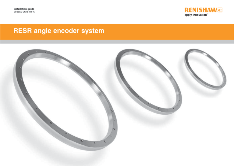
Installation guide
M-9559-0675-04-A
high encoder
accuracy linear
encoder
RESRRSLM
angle
system
Patents
Features of Renishaw’s RESR angle encoder systems and similar products are the subjects of the
following patents and patent applications:
EP 1094302
EP 0748436
EP 0514081
JP 3,202,316
EP 826138
US 5,302,820
US 6,051,971
JP 506,211/1999
JP 248,895/1993
US 5,861,953
Storage and handling
The RESR is a non-contact optical encoder
that provides good immunity against
contaminants such as dust, fingerprints and
light oils.
EP 0543513
US 5,241,173
Further information
For further information relating to the installation of RESR angle encoder system, see also the
RESR Data sheet (Part number L-9517-9128) and the Data sheet and the Installation guide for the
readhead that you are using. These can be downloaded from our website www.renishaw.com and
are also available from your local representative.
This document may not be copied or reproduced in whole or in part, or transferred to any other
media or language, by any means without the prior written permission of Renishaw. The publication
of material within this document does not imply freedom from the patent rights of Renishaw plc.
However, in harsh environments such as
machine tool applications, protection should
be provided to prevent ingress of coolant
or oil.
Ring and readhead
N-heptane
CH3(CH2)5CH3
Disclaimer
RENISHAW HAS MADE CONSIDERABLE EFFORTS TO ENSURE THE CONTENT OF THIS
DOCUMENT IS CORRECT AT THE DATE OF PUBLICATION BUT MAKES NO WARRANTIES
OR REPRESENTATIONS REGARDING THE CONTENT. RENISHAW EXCLUDES LIABILITY,
HOWSOEVER ARISING, FOR ANY INACCURACIES IN THIS DOCUMENT.
Ring only (avoid contact with readhead)
Acetone
CH3COCH3
Methylated
Spirits
Propan-2-ol
CH3CHOHCH3
Chlorinated
Solvents
Ring only
+70 °C
-20 °C
+55 °C
0 °C
Storage <95% RH
Operating <80% RH
Installation drawing (‘A’ section)
Nominal
external
diameter (mm)
Line count
20 µm pitch
General outline and dimensions Dimensions and tolerances in mm
Mounting holes
DO
DI
40 µm pitch
(mm)
(mm)
DH (mm)
N
θ
30.04
30.00
40
6
30°
52
8 192
4 096
52.20
52.10
57
9 000
4 500
57.35
57.25
37.04
37.00
47
6
30°
75
11 840
5 920
75.40
75.30
55.04
55.00
65
6
30°
100
15 744
7 872
100.30
100.20
80.04
80.00
90
6
30°
103
16 200
8 100
103.20
103.00
80.04
80.00
90
6
30°
104
16 384
8 192
104.40
104.20
80.04
80.00
90
6
30°
115
18 000
9 000
114.70
114.50
95.04
95.00
105
6
30°
150
23 600
11 800
150.40
150.20
130.04
130.00
140
9
20°
180.04
180.00
190
12
15°
31 488
15 744
206
32 400
16 200
206.50
206.10
186.05
186.00
196
12
15°
209
32 768
16 384
208.80
208.40
186.05
186.00
196
12
15°
18 000
229.40
229.00
209.05
209.00
219
Section A-A
12
20 000
254.80
254.40
235.06
235.00
245
12
15°
300
47 200
23 600
300.40
300.20
280.06
280.00
290
16
11.25°
350
55 040
27 520
350.40
350.20
330.06
330.00
340
16
11.25°
413
64 800
32 400
412.70
412.30
392.08
392.00
402
18
10°
380.10
380.00
390
18
10°
510.10
510.00
520
20
9°
65 536
32 768
550
86 400
43 200
550.20
549.80
10
2
15°
40 000
417
ØDH
ØDO
255
417.40
417.00
A
ØDI
200
36 000
A
N holes equally
spaced on PCD
ØDH Ø3.5
through c/bore
Ø6 x 3 deep
θ
200.40
200.20
229
N holes equally spaced
on PCD ØDH M3 x 0.5
through c/bore
Ø3.5 x 4 deep
0.5 x 45° 2 positions
6
Scale
15°
3
Note: θ is the angle between one tapped hole and
the adjacent clearance hole. For example, the angle
between two clearance holes is 2θ.
Nominal
external
diameter (mm)
20 µm pitch
75
100
Line count
General outline and dimensions Dimensions and tolerances in mm
Mounting holes
DO
DI
40 µm pitch
(mm)
(mm)
DH (mm)
N
θ
11 840
5 920
75.40
75.30
55.04
55.00
61
6
30°
15 744
7 872
100.30
100.20
80.04
80.00
86
6
30°
130.04
130.00
136
9
20°
180.04
180.00
186
12
15°
150
23 600
11 800
150.40
150.20
200
31 488
15 744
200.40
200.20
N holes equally spaced
on PCD ØDH
M3 x 0.5 through
A
N holes equally
spaced on
PCD ØDH
Ø3.5 through
A
θ
Installation drawing (‘B’ section)
ØDI
ØDH
ØDO
Note: θ is the angle between one tapped hole and
the adjacent clearance hole. For example, the angle
between two clearance holes is 2θ.
Section A-A
7
2.5 x 45°
0.5
6
Scale
6.5
R0.5
3
RGH20 mounted on ‘A’ section ring
RGH20 reference mark options
General outline and dimensions. Dimensions and tolerances in mm.
General outline and dimensions. Dimensions and tolerances in mm.
For RGH20 installation refer to Installation guide M-9561-0005.
1. Using A-9559-0650
2. Using A-9531-0250
2.2
(Yaw tol. ± 0.5°)
Ring centreline and
readhead optical
centreline
12.8
0.3
A-9559-0650
7.55
Ring centreline and
readhead optical centreline
Nominal ring
diameter +21.5 max
11.6
5.5
14
4.1
A-9531-0250
4.6
9.75
Set-up LED
19
(except RGH20F)
Nominal ring
diameter -18 min
10
7.5
0.65
7.5
10.5
15
M3 x 0.5 x 10 long
into any existing
tapped hole
11.75
Use A-9531-0342
adhesive to affix
reference mark
actuator
>4
15.6 (for RGH20 variants D, X, Z, W, Y, H, I, O, B)
11.3 (for RGH20 variant F)
7
36
13.5
22.5
>R20 dynamic bend radius
>R10 static bend radius
6.75
3
16.5
9.5
2 Mounting holes
M3 x 0.5 through
11.6
22.1
ax
m
4.4
Ø
(Roll tol. ± 1°)
4. Using A-9531-0287
3. Using A-9541-0037
1.1
(Pitch tol. ± 1°)
3.8
A-9541-0037
3
3
10.75
0.6 A
0.5
0.09
4.8
7.8
0.8 ± 0.08
Reference mark sensor position
Ring centreline and
readhead optical centreline
Ring centreline and
readhead optical centreline
22.6
A
18.6
0.2
Ring centreline and
readhead optical
centreline
Ring centreline and
readhead optical
centreline
Datum A passes through
RESR centre of rotation
A-9531-0287
9.75
4.6
27
6
2.2
3
0.6
2.15
M3
2.3 8.5
3
8
M3 screw, button head
RGH34 mounted on ‘A’ section ring
RGH34 reference mark options
General outline and dimensions. Dimensions and tolerances in mm.
General outline and dimensions. Dimensions and tolerances in mm.
For RGH34 installation refer to Installation guide M-9537-0194.
1. Using A-9559-0658
(Yaw tol. ± 1°)
2. Using A-9531-0250
Ring centreline
and readhead
optical centreline
1.3
0.2
10.5
7.5
90°
Ring centreline and
readhead optical centreline
7.5
4
7.5
Ø12.05 to 12.15 recommended
mounting hole size
15
8.3
Note: Extent of components
mounted on PCB
4.6
A-9559-0658
A-9531-0250
Nominal ring
diameter +16.5 max
5.5
(Roll tol. ± 1°)
0.09
4.1
10.5
7
7
2.2
Nominal ring
diameter -18 min
0.2
11
7
16.5
(Pitch tol. ± 1°)
0.8
9.2
14.2
7.1
8.5
11.5
7.5
0.8
10
M3 x 0.5 x 10 long
into any existing
tapped hole
12.5
7
Use A-9531-0342 adhesive to
affix reference mark actuator
1.5 ±0.15
Ring centreline and
readhead optical centreline
Ring centreline and
readhead optical centreline
9.5
12
2.2 0.5
10.5 10.5
Ø1 ground connection to case
for improved EMC performace
1
2
4. Using A-9531-0287
3. Using A-9541-0037
RGI34 interface (for use with above)
A-9541-0037
6
11.5
3
8.5
3
10
Ring centreline and
readhead optical centreline
6
Ring centreline and
readhead optical centreline
9
FPC cable. 50, 100 or 150 length
13.5
27
13.5
0.2
10.5 10.5
8
3.8
7.5 7.5
0.8
8.5
A-9531-0287
11
7
11
7
M3 Screw, 10.5
button head
2.3
8.6 8.2
2
2.1
35
M3
2.2
8
RGH40 mounted on ‘A’ section ring
RGH40 reference mark options
General outline and dimensions. Dimensions and tolerances in mm.
General outline and dimensions. Dimensions and tolerances in mm.
For RGH40 installation refer to Installation guide M-9550-0028.
1. Using A-9559-0666
2. Using A-9531-0250
Ring centreline and
readhead optical
centreline
Ring centreline
and readhead
optical centreline
8
(Yaw tol. ± 1°)
Mounting holes 2 off
M3 x 0.5 x 7.5 deep
0.8
7
0.2
A-9559-0666
14.2
14.8
Nominal ring
diameter +5.5 max
A-9531-0250
7
9.8
4
Mounting holes 2 off
M3 x 0.5 x 9.5 deep
2.2
Nominal ring
diameter -18 min
6
8
M3 x 0.5 x 12 long
11
11.5
7
Use A-9531-0342 adhesive to
affix reference mark actuator
15.5
3
11.9
22
22
19
19
3. Using A-9531-0287
Set-up LED
Ø4.7
(Roll tol. ± 1°)
4.8
17.8
0.13
11.4 12.3
11.4
Ring centreline and
readhead optical
centreline
7
2.8
6.5 6.5
0.8 ± 0.15
10
0.8
(Pitch tol. ± 1°)
Ring centreline and
readhead optical centreline
8
Ring centreline and
readhead optical centreline
7
7
M3 screw,
button head
0.2
11
11
A-9531-0287
2.2
0.5
Please note that the A-9541-0037 and
A-9546-0160 reference mark assemblies
cannot be used with RGH40 readheads
because this could potentially
result in a collision.
Taper mount method Step 2
Select a mounting option
Taper mount
Clean shaft taper and internal taper of RESR
as recommended in the storage and handling
section.
Interference fit
‘A’ section
Use 4 equally spaced M3 screws
(on RESR sizes 52 mm to 150 mm use
3 screws).
‘B’ section
Note: Do not lubricate screws.
Insert the screws so that the RESR is loosely
connected to the shaft, then roughly align the
ring by eye and touch.
Not
applicable
Lightly tighten the screws. Use a Dial
Test Indicator (DTI) to check the radial
displacement at the screw locations.
Notes
Recommended for all installations
Enables simplest adjustment.
Offers highest accuracy.
Enables eccentricity to be compensated.
Offers excellent mechanical stability against
thermal cycling, shock and vibration.
Minimises cost of substrate preparation.
Note: Disregard the radial displacement
between the screw locations.
Alternative installation
Will not correct eccentricity of
the supporting shaft.
DTI
DT
Taper mount method Step 1
Mounting shaft specifications
Use a DTI with low exertion force to avoid
scratching the scale surface. A DTI with a
ruby ball stylus is recommended as a further
precaution against scratches.
15° ± 0.2°
7 min
0.5*
Adjust the screws so the radial displacement is the same at each screw location.
*For 417 mm and 550 mm rings only, 1.0
Recommended taper roundness
When adjusting, identify the screw location with the lowest radial displacement and tighten that
screw, aiming for the average of the highest and lowest indicator readings.
Recommended taper diameter (DT)
Diameter
(mm)
Roundness value
(mm TIR)
DO
(mm)
DT
(mm)
DO
(mm)
DT
(mm)
DO
(mm)
DT
(mm)
52
33.85
33.65
40.85
40.65
58.85
58.65
83.85
83.65
83.85
83.65
83.85
83.65
115
98.85
98.65
133.85
133.65
183.85
183.65
189.85
189.65
189.85
189.65
212.85
212.65
255
238.85
238.65
283.85
283.65
333.85
333.65
395.85
395.65
383.85
383.65
513.85
513.65
115
0.025
150 to 255
0.050
300
0.075
57
75
Recommended surface finish
Ra value is 1.2 µm or better
100
103
104
150
200
206
209
229
DO = Nominal external diameter
300
350
413
417
550
Repeat this process until the DTI readings are within ±15 µm at the screw locations.
NOTE: At this stage, the screws
should only be lightly tightened
(approximately 0.5 Nm) to allow
further final adjustment.
Taper mount method
Taper mount method
Step 3
Insert the next 4 screws (on RESR sizes 52 mm to
150 mm insert the next 3 screws).
Adjust all the screws inserted thus far, so that
the radial displacement at each screw location is
within ±15 µm.
Again, at this stage, the screws should only be
lightly tightened.
Diameter
(mm)
Torque (Nm)
115
1.5
150 to 255
1.25
300
1.0
min
Step 6
Finally, ensure that all the screws are tightened to the torque
recommendations (see table).
When torquing-up the screws, follow the method used in Step 5.
Continue the torquing process until all of the screws are set to the
minimum recommended torque.
If some of the screws seem loose, continue the torquing process,
but aim to adjust the screw with the lowest radial deflection to a
point which is just above the average radial deflection.
Note: You may notice that the torque required to
achieve the radial displacement tolerance will be
slightly higher during step 3 than during step 2.
This is normal.
Ensure that the radial deflection at the screw locations is
within ± 3 µm.
Further fine tuning can improve the installed accuracy.
Taper mount method
Excessive tightening of screws can have a small effect on accuracy.
Please contact your local representative for more details.
Step 4
Interference fit method
Insert the remaining screws.
Mounting shaft specifications.
DO
(mm)
Adjust all of the screws inserted thus far, so that
the radial displacement at each screw location is
within ±15 µm.
52
57
75
100
DO
Taper mount method
Step 5
DS
103
104
115
Rotate the RESM ring, measuring the radial displacement at all of the screw locations.
Tighten the screw with the lowest radial displacement so that it matches the average radial
displacement.
Again, rotate the RESM ring and re-check the radial displacement at all of the screw locations,
tightening the screw with the lowest radial displacement so that it matches the average.
Repeat this process until the radial displacement at all of the screw locations is
within ± 3 µm.
150
DS
(mm)
30.028
30.015
37.028
37.015
55.039
55.020
80.045
80.023
80.045
80.023
80.045
80.023
95.045
95.023
130.052
130.027
DO
(mm)
200
206
209
229
255
300
350
413
DS
(mm)
180.052
180.027
186.060
186.031
186.060
186.031
209.060
209.031
235.060
235.031
280.066
280.034
330.073
330.037
392.073
392.037
NOTE: 417 and 550 mm rings should be
taper mounted only.
DO = Nominal external diameter
DS = Recommended shaft diameter to enable
transition fit
Renishaw plc
New Mills, Wotton-under-Edge,
Gloucestershire, GL12 8JR
United Kingdom
T +44 (0)1453 524524
F +44 (0)1453 524901
E uk@renishaw.com
www.renishaw.com
For worldwide contact details,
please visit our main website at
www.renishaw.com/contact
RENISHAW® and the probe emblem used in the RENISHAW logo are
registered trademarks of Renishaw plc in the UK and other countries.
apply innovation is a trademark of Renishaw plc.
© 2001-2009 Renishaw plc
All rights reserved
Issued 0209
*M-9559-0675-04*


