Experiment # 3 Node-Voltage and Mesh
advertisement

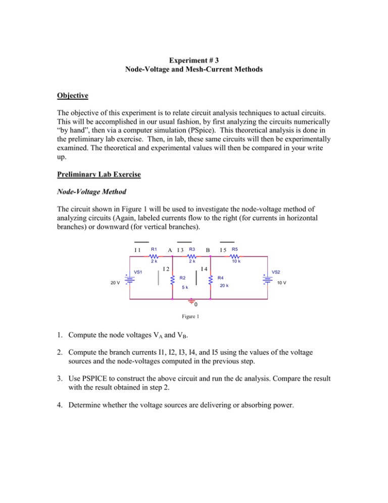
Experiment # 3 Node-Voltage and Mesh-Current Methods Objective The objective of this experiment is to relate circuit analysis techniques to actual circuits. This will be accomplished in our usual fashion, by first analyzing the circuits numerically “by hand”, then via a computer simulation (PSpice). This theoretical analysis is done in the preliminary lab exercise. Then, in lab, these same circuits will then be experimentally examined. The theoretical and experimental values will then be compared in your write up. Preliminary Lab Exercise Node-Voltage Method The circuit shown in Figure 1 will be used to investigate the node-voltage method of analyzing circuits (Again, labeled currents flow to the right (for currents in horizontal branches) or downward (for vertical branches). I1 R1 A I3 2k VS1 R3 B I5 2k I2 10 k I4 R2 R5 VS2 R4 20 V 20 k 5k 10 V 0 Figure 1 1. Compute the node voltages VA and VB. 2. Compute the branch currents I1, I2, I3, I4, and I5 using the values of the voltage sources and the node-voltages computed in the previous step. 3. Use PSPICE to construct the above circuit and run the dc analysis. Compare the result with the result obtained in step 2. 4. Determine whether the voltage sources are delivering or absorbing power. Mesh-Current Method The circuit shown in Figure 2 will be used to investigate the mesh-current method of analyzing circuits. 1. Compute the mesh-currents IA, IB, and IC (they flow clockwise around the indicated loops). 2. Compute the branch currents I1, I2, I3, I4, and I5 using the values of the meshcurrents computed in the previous step. I1 R1 I3 2k IA I5 2k I2 VS1 20 V R3 R5 10 k I4 R2 IB VS2 R4 20 k 5k IC 10 V 0 Figure 2 3. Use PSPICE to construct the above circuit and run the dc analysis. Compare the result with the result obtained in step 2. 4. Determine whether the voltage sources are delivering or absorbing power. Procedure The circuits of Figures 1 and 2 will now be used to verify the node-voltage and meshcurrent methods, respectively. Node-Voltage Method 1. Construct the circuit shown in Figure 1. 2. Measure the node-voltages VA and VB using digital multi-meter in the voltmeter mode. 3. Measure the branch currents I1, I2, I3, I4, and I5 using a properly connected digital multi-meter in ammeter mode. 2 Mesh-Current Method 1. Construct the circuit shown in figure 2. 2. Measure the branch currents I1, I2, I3, I4, and I5 using a properly connected digital multi-meter in the ammeter mode. Analysis Node-Voltage Method 1. Compare the measured values of the node-voltages VA and VB with the theoretical values. 2. Compare the measured values of the branch currents I1, I2, I3, I4, and I5 with the theoretical values. Mesh-Current Method 1. Compute the value of the mesh-currents IA, IB, and IC from the measured branch currents and compare with the theoretical values. 2. Compare the measured values of the branch currents I1, I2, I3, I4, and I5 with the theoretical values. 3


