UNIDUCT ® 2700/2800/2900
Wiremold Electrical Systems conform to and should be
installed and properly grounded in compliance with requirements of the current National Electrical Code, Canadian
Electrical Code, or codes administered by local authorities.
All electrical products may represent possible shock or fire
hazard if improperly installed or used. Wiremold electrical
products are UL listed, made for interior use only, and should
be installed in conformance with current local and/or the
National Electrical Code.
Surface Nonmetallic Latching Raceway System
INSTALLATION INSTRUCTIONS
Installation Instruction No.: 40307R2 – Updated July 2005
CAUTION: For Low Voltage (50V or Less).
DATA COMMUNICATION WIRING
The following procedure is recommended.
1. Chalk a path that raceway will follow.
2. Mark points where boxes will be installed.
3. Determine length of run from each box or corner. (Measure runs from side to side of boxes.)
4. Start from the feed point.
5. Peel release paper from adhesive strip and mount Uniduct raceway immediately to surface. (Adhesive-backed Uniduct raceway
should be mounted to clean, dry, grease-free, smooth surface.) Apply pressure along entire raceway to ensure proper adhesion.
For irregular or uneven surfaces, mechanical mounting may be necessary for best results.
6. Commence wiring. As you go along the length, push the wire into the open end of the Uniduct raceway and snap it closed. Use
appropriate fittings wherever needed. (See illustrations.)
7. Uniduct raceway can be painted with acrylic latex paints to match the surrounding surface. Follow the application recommendations
of each individual paint manufacturer.
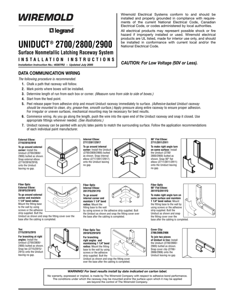
External Elbow:
2718/2818/2918
Internal Elbow:
2717/2817/2917
90° Flat Elbow:
2711/2811/2911
To go around external
corner: Install the
Uniduct (2700/2800/2900) butted as shown.
Snap external elbow
(2718/2818/2918)
onto the Uniduct
leaving no gap.
To go around internal
corner: Install the Uniduct
(2700/2800/2900) butted
as shown. Snap internal
elbow (2717/2817/2917)
onto the Uniduct leaving
no gap.
To make right angle turn
on same surface: Install
the Uniduct (2700/
2800/2900) butted as
shown. Snap 90° flat
elbow (2711/2811/2911)
onto the Uniduct leaving
no gap.
Fiber Optic
External Elbow:
2818FO/2918FO
Fiber Optic
Internal Elbow:
2817FO/2917FO
Fiber Optic
90° Flat Elbow:
2811FO/2911FO
To go around external
corner and maintain
1 1/4" bend radius:
Mount the fitting base
to the wall by using
screws or the adhesive
strip supplied. Butt the
Uniduct as shown and snap the fitting cover over the
base after the cabling is completed.
To go around
internal corner and
maintain 1 1/4" bend
radius: Mount the
fitting base to the wall
by using screws or the adhesive strip supplied. Butt
the Uniduct as shown and snap the fitting cover over
the base after the cabling is completed.
To make right angle turn on
same surface and maintain
1 1/4" bend radius: Mount
the fitting base to the wall by
using screws or the adhesive
strip supplied. Butt the
Uniduct as shown and snap
the fitting cover over the
base after the cabling is completed.
Tee:
2715/2815/2915
Fiber Optic Tee:
2815FO/2915FO
Cover Clip:
2706/2806/2906
For branching at right
angles: Install the
Uniduct (2700/2800/2900) butted as shown.
Snap tee (2715/2815/2915) onto the Uniduct
leaving no gap.
For branching
right angles and
maintaining 1 1/4" bend
radius: Mount the fitting
base to the wall by using
screws or the adhesive
strip supplied. Butt the
Uniduct as shown and snap the fitting cover
over the base after the cabling is completed.
To join two pieces
of Uniduct in line: Install
the Uniduct (2700/2800/2900) butted as shown.
Snap cover clip (2706/2806/2906) onto the
Uniduct leaving no gap.
WARNING! For best results install by date indicated on carton label.
No warranty, expressed or implied, is made by The Wiremold Company with respect to adhesive bond performance.
The conditions under which the raceway may be mounted and/or the surface upon which it may be applied
are beyond the control of The Wiremold Company.
Blank End Fitting:
2710B/2810B/2910B
Reducing Connector:
2889/2989/2989A
Drop Ceiling Connector:
2786/2886/2986
To cover the open
end of the Uniduct:
Snap the blank end
fitting (2710B/2810B/
2910B) onto the open
end of (2700/2800/
2900) Uniduct.
To go from larger to smaller Uniduct:
Install the Uniduct (2700/2800/2900)
butted as shown. Snap the reducing
connector (2889/2989/2989A) onto
the Uniduct leaving no gap. Snap
cover clip (2706/2806/2906) over
connection. When reducing from a
fitting to raceway, cover clip is
not required.
For bringing cables from
ceiling to raceway: Cut a hole
in the ceiling tile right next to
the metal grid. Drop the cables
from the ceiling into the Uniduct.
Push the drop ceiling connector
(2786/2886/2986) through the
hole so that the notch in the
large end of the connector butts
with the metal grid. Snap the
drop ceiling connector
(2786/2886/2986) onto the
Uniduct (2700/2800/2900).
TYPICAL PROCEDURE FOR INSTALLING
DEVICE BOXES
1. Remove proper tongue on the device box (NM2048)
base. (See Figure 1.)
2. Notch proper knockout in cover using knife. (See
Figure 2.) Use pliers to remove knockout inward
for cleaner edge. (Trimming may be necessary.)
3. Fasten device box base to wall using screws
(not provided).
4. Snap device box cover onto the base.
5. Mount device box and faceplate.
2800
Tongues
2700
2900
Cover Side View
Base Front View
Figure 1
NM2048 Cover
NM2048 Base
Faceplate
Cover
Front View
Figure 2
2700/2800/2900
Uniduct
Figure 3
Wiremold / Legrand
U.S. and International:
60 Woodlawn Street • West Hartford, CT 06110
1-800-621-0049 • FAX 860-232-2062 • Outside U.S. 860-233-6251
Canada:
570 Applewood Crescent • Vaughan, Ontario L4K 4B4
1-800-723-5175 • FAX 905-738-9721
© Copyright 2005 Wiremold / Legrand All Rights Reserved
40307R2 – Updated July 2005 – For latest specs visit www.wiremold.com


