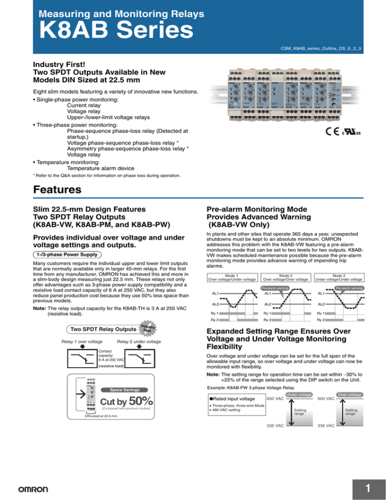
Measuring and Monitoring Relays
K8AB Series
CSM_K8AB_series_Outline_DS_E_3_3
Industry First!
Two SPDT Outputs Available in New
Models DIN Sized at 22.5 mm
Eight slim models featuring a variety of innovative new functions.
• Single-phase power monitoring:
Current relay
Voltage relay
Upper-/lower-limit voltage relays
• Three-phase power monitoring:
Phase-sequence phase-loss relay (Detected at
startup.)
Voltage phase-sequence phase-loss relay *
Asymmetry phase-sequence phase-loss relay *
Voltage relay
• Temperature monitoring:
Temperature alarm device
* Refer to the Q&A section for information on phase loss during operation.
Features
Slim 22.5-mm Design Features
Two SPDT Relay Outputs
(K8AB-VW, K8AB-PM, and K8AB-PW)
Provides individual over voltage and under
voltage settings and outputs.
1-/3-phase Power Supply
Many customers require the individual upper and lower limit outputs
that are normally available only in larger 45-mm relays. For the first
time from any manufacturer, OMRON has achieved this and more in
a slim-body design measuring just 22.5 mm. These relays not only
offer advantages such as 3-phase power supply compatibility and a
resistive load contact capacity of 6 A at 250 VAC, but they also
reduce panel production cost because they use 50% less space than
previous models.
Note: The relay output capacity for the K8AB-TH is 3 A at 250 VAC
(resistive load).
Two SPDT Relay Outputs
Relay 1 over voltage
Industry
First
Relay 2 under voltage
Contact
capacity:
6 A at 250 VAC
(resistive load)
Pre-alarm Monitoring Mode
Provides Advanced Warning
(K8AB-VW Only)
In plants and other sites that operate 365 days a year, unexpected
shutdowns must be kept to an absolute minimum. OMRON
addresses this problem with the K8AB-VW featuring a pre-alarm
monitoring mode that can be set to two levels for two outputs. K8ABVW makes scheduled maintenance possible because the pre-alarm
monitoring mode provides advance warning of impending trip
alarms.
Mode 1
Over voltage/Under voltage
Mode 2
Over voltage/Over voltage
Mode 3
Under voltage/Under voltage
Pre-alarm warning
Pre-alarm warning
AL1
AL1
AL1
AL2
AL2
AL2
Ry 1
Ry 1
Ry 1
Ry 2
Ry 2
Ry 2
Expanded Setting Range Ensures Over
Voltage and Under Voltage Monitoring
Flexibility
Over voltage and under voltage can be set for the full span of the
allowable input range, so over voltage and under voltage can now be
monitored with flexibility.
Note: The setting range for operation time can be set within −30% to
+25% of the range selected using the DIP switch on the Unit.
Space Savings
Cut by 50%
(Compared with previous models)
Example: K8AB-PW 3-phase Voltage Relay
●Rated input voltage
Under voltage
600 VAC
• Three-phase, three-wire Mode
• 480-VAC setting
Over voltage
600 VAC
Setting
range
DIN-sized at 22.5 mm
336 VAC
Setting
range
336 VAC
1
K8AB Series
Usable as a Simple Sensor Controller
DIN Track Mounting
Accepts inputs of 4 to 20 mA or 0 to 10 V.
Gang-mounting is also possible.
Compatible with Commercial CTs
The K8AB-AS 1-Phase Current Relay can be used with commercial
CTs for current measurement.
CT current on
secondary side
Commercial CTs
0 to 1 A AC
Applicable model
K8AB-AS2
0 to 5 A AC
Note: OMRON-compatible CT: K8AC-CT200L Only the K8AB-AS3
can be used for AC operation at both 100 and 200 A.
DIP Switch Function Selection
Various relay functions can be selected using a DIP switch. This
means that the number of models required can be reduced to 1/8
what it had been simply by installing a relay like the K8AB-AS. An
added advantage is that it reduces the inventory of maintenance
parts.
Manual reset
Checking the operating status has never been convenient because of
the time it takes to reach the preset operation time. The K8AB
eliminates this problem by featuring a flashing alarm indicator that
clearly indicates the operating status. This has greatly simplified the
task of checking on-site status particularly when operation settings
are changed or an error occurs.
Note: Excluding the K8AB-PH and K8AB-TH.
Example: K8AB-AS 1-Phase Current Relay
DIP switch
Resetting
method
SW2
ON
Function
OFF
Automatic reset
Relay drive SW3
method
ON
Normally open
OFF
Normally closed
Operating
mode
ON
Over current
OFF
Under current
SW4
Operation Level Indication by Flashing
Alarm Indicator
Over voltage
Going to
trip soon!
Input
Under voltage
Ry1
Note: 1. The operating time can be set to 0.1
to 30 s.
2. SW1 of K8AB-AS is not used.
Ry2
Flashing
Single K8AB Monitors 3-phase Power
Supply with 3 or 4 Wires
(K8AB-PM, K8AB-PA, and K8AB-PW)
Lit
OMRON Low-voltage Monitoring Relays can be used to monitor 3phase power supplies with 3 or 4 wires simply by changing DIP
switch settings.
Phase to phase voltage (3 wires)
L1
L2
Phase to neutral voltage (4 wires)
L3
L1
L2
L3
N
230 VAC
400 VAC
400 VAC
A Single K8AB Can Monitor a 3-phase
Power Supply Anywhere in the World
Reduces Maintenance Parts Inventory
SW3
SW4
K8AB-P@2
SW2
Operation time
Operation time
Ideal for Monitoring Current or Voltage
Current Monitoring Applications (Single Phase)
K8AB-AS2 can use standardized CT!!
Application
Measured
current
Applicable
models
Operating value
setting range
Simple Sensor 4 to 20 mA DC K8AB-AS1
Controller
2 to 20 mA AC/DC
Process
control signal
monitoring
(using a
standardized
CT)
0.1 to 1 A AC/DC
10 to 100 mA AC/DC
50 to 500 mA AC/DC
230 VAC
SW2
Indicates a continuous
trip.
Notification by
Flashing Alarm
Indicator
230 VAC
400 VAC
K8AB-P@1
The trip alarm operates
when the input reaches
the operation range and
the preset operation
time has elapsed.
ON
ON
OFF
OFF
ON
OFF
ON
OFF
ON
P-N
138 V 133 V 127 V 115 V
OFF
P-P
240 V 230 V 220 V 200 V
ON
P-N
277 V 240 V 230 V 220 V
OFF
P-P
480 V 415 V 400 V 380 V
0 to 1 A AC
0 to 5 A AC
K8AB-AS2
Current
0 to 200 A AC K8AB-AS3
monitoring for
(See note.)
motors and
heaters
(using a
special CT)
0.5 to 5 A AC/DC
0.8 to 8 A AC/DC
--10 to 100 A AC
20 to 200 A AC
Note: Special CT model: OMRON K8AC-CT200L
2
K8AB Series
Wire Connection
Voltage Monitoring Applications (Single Phase)
Application
Measured
voltage
Applicable
models
Operating value
setting range
2 × 2.5 mm2 solid or 2 × 1.5 mm2 standard ferrules.
Direct
0 to 60 mV DC K8AB-VS1
current
0 to 100 mV DC K8AB-VW1
monitoring 0 to 150 mV DC
(monitoring
the output
voltage of a
shunt)
6 to 60 mV AC/DC
Compliance with International Standards
10 to 100 mV AC/DC
A third party has certified CE mark compliance. This device is in
compliance with UL certification requirements.
Power
supply line
monitoring
1 to 10 V AC/DC
12 VDC
24 VDC
100 VAC
115 VAC
K8AB-VS2
K8AB-VW2
200 VAC
230 VAC
400 VAC
480 VAC
K8AB-VS3
K8AB-VW3
30 to 300 mV AC/DC
3 to 30 V AC/DC
15 to 150 V AC/DC
20 to 200 V AC/DC
30 to 300 V AC/DC
60 to 600 V AC/DC
Selection Guide
Product name
1-Phase Current Relay
Model
K8AB-AS1
K8AB-AS2 *1
K8AB-AS3 *2
Nominal input
I1-COM: 2 to 20 mA AC/DC
I2-COM: 10 to 100 mA AC/DC
I3-COM: 50 to 500 mA AC/DC
I1-COM: 0.1 to 1 A AC/DC
I2-COM: 0.5 to 5 A AC/DC
I3-COM: 0.8 to 8 A AC/DC
I2-COM: 10 to 100 A AC
I3-COM: 20 to 200 A AC
Supply voltage
24 V AC/DC
100 to 115 VAC
200 to 230 VAC
24 V AC/DC
100 to 115 VAC
200 to 230 VAC
24 V AC/DC
100 to 115 VAC
200 to 230 VAC
24 V AC/DC
100 to 115 VAC
200 to 230 VAC
24 V AC/DC
100 to 115 VAC
200 to 230 VAC
24 V AC/DC
100 to 115 VAC
200 to 230 VAC
24 V AC/DC
100 to 115 VAC
200 to 230 VAC
24 V AC/DC
100 to 115 VAC
200 to 230 VAC
24 V AC/DC
100 to 115 VAC
200 to 230 VAC
Same as the input
voltage.
1-Phase Voltage Relay
K8AB-VW3
Phase-sequence, Phase-loss Relay *3
3-Phase Voltage, Phase-sequence,
Phase-loss Relay
3-Phase Asymmetry,
Phase-sequence, Phase-loss Relay
3-Phase Voltage Relay
K8AB-PH1
K8AB-PM1
K8AB-PM2
K8AB-PA1
K8AB-PA2
K8AB-PW1
K8AB-PW2
V1-COM: 6 to 60 mV AC/DC
V2-COM: 10 to 100 mV AC/DC
V3-COM: 30 to 300 mV AC/DC
V1-COM: 1 to 10 V AC/DC
V2-COM: 3 to 30 V AC/DC
V3-COM: 15 to 150 V AC/DC
V1-COM: 20 to 200 V AC/DC
V1-COM: 30 to 300 V AC/DC
V1-COM: 60 to 600 V AC/DC
V1-COM: 6 to 60 mV AC/DC
V2-COM: 10 to 100 mV AC/DC
V3-COM: 30 to 300 mV AC/DC
V1-COM: 1 to 10 V AC/DC
V2-COM: 3 to 30 V AC/DC
V3-COM: 15 to 150 V AC/DC
V1-COM: 20 to 200 V AC/DC
V1-COM: 30 to 300 V AC/DC
V1-COM: 60 to 600 V AC/DC
200 to 500 VAC
200, 220, 230, or 240 VAC
380, 400, 415, or 480 VAC
200, 220, 230, or 240 VAC
380, 400, 415, or 480 VAC
200, 220, 230, or 240 VAC
380, 400, 415, or 480 VAC
Temperature Monitoring Relay
K8AB-TH11S
Thermocouple/Pt100 (0 to 399°C/°F)
100 to 240 VAC
K8AB-TH12S
Thermocouple (setting unit of 10°C/°F)
K8AB-TH11S
K8AB-TH12S
Thermocouple/Pt100 (0 to 399°C/°F)
100 to 240 VAC
24 V AC/DC
Thermocouple (setting unit of 10°C/°F)
24 V AC/DC
K8AB-VS1
1-Phase Voltage Relay
K8AB-VS2
K8AB-VS3
K8AB-VW1
K8AB-VW2
Output relays
One SPDT relay
Housing
DIN 22.5 mm
One SPDT relay
Two SPDT relays
One SPDT relay
Two SPDT relays
One SPDT relay
Two SPDT relays
One SPDT relay
*1 K8AB-AS2 can use standardized CT.
*2 The K8AC-CT200L CT is required to use with K8AB-AS3.
*3 K8AB-PH can detect the phase-loss during motor operation.
3
K8AB Series
Model Number Structure
K8AB-@@
1
2 3
1. Basic Model
Notation
K8AB
Meaning
Measuring and Monitoring Relays
2. Functions
Notation
AS
Meaning
Operation
Single-phase Current Relay
Datasheet available
One-sided operation
Yes
Yes
VS
Single-phase Voltage Relay
One-sided operation
VW
Single-phase Upper-/lower-limit
Voltage Relay
Simultaneous upper and Yes
lower limit monitoring
PH
Phase-sequence Phase-loss Relay
---
PM
Three-phase Voltage Phase-sequence Simultaneous upper and Yes
Phase-loss Relay
lower limit monitoring
PA
Three-phase Asymmetry Phasesequence Phase-loss Relay
---
PW
Three-phase Voltage Relay
Simultaneous upper and Yes
lower limit monitoring
Yes
Yes
3. Rated Operating Power
Note: For details, refer to the relevant Ordering Information.
K8AB-TH1@@
2
3 4
2. Functions
Notation
TH1
Meaning
Temperature Alarm Device
Operation
One-sided operation
3. Setting range
Notation
Meaning
1
Low temperature range (0 to 399°C set in increments of 1°C)
2
High temperature range (0 to 1700°C set in increments of 10°C)
4. Output form
Notation
S
Meaning
One SPDT relay output
4
K8AB Series
Application Examples
Chain Breakage Protection for Conveyors
K8AB-AS
K8AB-VS
Battery Voltage Checking
K8AB-AS2 can use standardized CT!!
L1 L2 L3
Alarm
Relay output:
6 A at 250 VAC
(resistive load)
Alarm
CT Over current detection
K8AB-AS
Instantaneous over
current monitoring
K8AB-VS
Under voltage
monitoring
Battery
Motor
●Purpose
●Purpose
The K8AB-VS is used to check battery charge
levels.
Fo
r
ob eign
j ec
t
When the motor locks up, its rotational torque
may break the chain. To prevent that from
happening, the relay must trip the instant it
detects a motor lock error. A thermal relay
cannot be used for chain protection because it
takes too long to start operating.
Locked conveyor
●Advantages
The K8AB-VS can detect when the battery
charge is low.
●Advantages
The K8AB-AS offers effective alarms because
it starts operating in 0.1 s or less.
(If a motor is used as the load, be careful that the inrush current does not exceed
the allowable input range.)
Protection against Idle Running of a
Submersible Pump
Monitoring the Control Power Supply at
Communication Bases
K8AB-VW
K8AB-VW
Over and Under Voltage
Monitoring
K8AB-AS
220 VAC
K8AB-AS2 can use standardized CT!!
L1 L2 L3
Wireless
communications
base
Alarm
Relay output:
6 A at 250 VAC
(resistive load)
Alarm
Power supply
monitoring
24 VDC
CT Under current detection
Over voltage
K8AB-AS
Under current
monitoring
Voltage
input level
Under voltage
A submersible pump will malfunction if it
begins to operate out of water, so
instantaneous detection of this kind of idle
operation is essential.
Lit
Flashing
T1
Lit
T
T
T: Operation time (0.1 to 30 s)
T1: 1 s or 5 s selection (Timer when the control power supply is turned ON.)
●Advantages
Idle pump operation
The K8AB-AS can detect idle pump
operation by detecting under current levels.
K8AB-AS
Bulb Burnout Detection
●Purpose
Communications bases must be carefully monitored because the effects of a
power outage or voltage drop would be highly detrimental to communications.
This is why the K8AB-VW monitors the control panel power supply for over
voltage and under voltage levels.
●Advantages
It can detect over voltage and under voltage as well as output individual over
voltage and under voltage alarms using SPDT relays.
K8AB-AS2 can use standardized CT!!
Power
supply
Under voltage
alarm indicator
Over voltage
alarm relay
Under voltage
alarm relay
●Purpose
Submersible
pump
Flashing
Over voltage
alarm indicator
Pump
K8AB-AS
Under current
monitoring
Under current detection
Bulb
External CT L
L
L
L
L
●Purpose
The K8AB-AS is used to detect burned out light bulbs.
●Advantages
The K8AB-AS can detect burned out light bulbs by
detecting under current levels. The Relay's sensitivity
can be adjusted to detect burned out light bulbs even in
applications where multiple light bulbs are used.
5
K8AB Series
Monitoring Phase Sequence/
Phase Loss for Escalators
K8AB-PH
High voltage
reception
L1 L2 L3
Can detect the phase-loss during motor operation!!
L1 L2 L3
K8AB-PW
Monitoring Generated Voltage
Relay output:
6 A at 250 VAC
(resistive load)
Generator
monitoring panel
Power grid panel
OCR, RPR
UVR, OVR
PLC
K8AB-PH
Phase-sequence and
phase-loss monitoring
Power grid
protection relay
Contactor
Generator
●Purpose
The K8AB-PH detects the phase sequence or
phase loss in escalator power supplies.
K8ABA-PW
3-Phase voltage
monitoring
●Advantages
A single K8AB-PH can detect the phase
sequence or phase loss at startup.
●Purpose
Motor
The K8AB-PW monitors the voltage of power generated by a
generator. It also detects over voltage and under voltage in power
from a generator.
Monitoring Compressor Power Supplies
K8AB-PM
L1 L2 L3
Fixed type
Mobile type
Load
●Advantages
A single K8AB-PW can monitor 3-phase voltage. It can also
output individual alarms for over voltage and under voltage using
SPDT relays because it features two outputs with SPDT relays.
The voltage measurement range can be switched from 200 to 480
VAC and the K8AB-PW can be switched to monitor phase voltage
or line voltage.
Monitoring Voltage Generated by
Wind-powered Generators
K8AB-PW
Relay output:
6 A at
250 VAC
(resistive
load)
●Purpose
J7L Contactor
The K8AB-PW detects over voltage and under
voltage in power generated by a wind-powered
generator.
●Purpose
Compressors cannot operate correctly under
conditions such as under voltage, asymmetry voltage,
phase loss, or phase sequence. The K8AB-PM can be
used to monitor 3-phase voltage, the phase sequence,
and phase loss.
●Advantages
A single K8AB-PM can monitor over voltage, under
voltage, the phase sequence and phase loss in
3-phase voltage. It can also output individual alarms for
over voltage or under voltage using an SPDT relay.
The K8AB-PM is able to recognize which alarm has
occurred.
●Advantages
Load
A single K8AB-PW can be used for a 3-phase power
supply with 3 or 4 wires. It can be used to individually
set and output over voltage and under voltage
alarms.
K8AB-PM
3-Phase voltage,
phase-sequence,
and phase-loss monitoring
L1
L2
L3
N
Wind-powered generator
K8AB-PW
Simultaneous 3-phase
over and under voltage
monitoring
The application examples provided in this catalog are for reference only. Check functions and safety of the equipment before use.
Never use the products for any application requiring special safety requirements, such as nuclear energy control systems, railroad systems, aviation systems, medical equipment,
amusement machines, vehicles, safety equipment, or other application involving serious risk to life or property, without ensuring that the system as a whole has been designed to address
the risks, and that the OMRON products are properly rated and installed for the intended use within the overall equipment or system.
ALL DIMENSIONS SHOWN ARE IN MILLIMETERS.
To convert millimeters into inches, multiply by 0.03937. To convert grams into ounces, multiply by 0.03527.
In the interest of product improvement, specifications are subject to change without notice.
6
Terms and Conditions Agreement
Read and understand this catalog.
Please read and understand this catalog before purchasing the products. Please consult your OMRON representative if you
have any questions or comments.
Warranties.
(a) Exclusive Warranty. Omron’s exclusive warranty is that the Products will be free from defects in materials and workmanship
for a period of twelve months from the date of sale by Omron (or such other period expressed in writing by Omron). Omron
disclaims all other warranties, express or implied.
(b) Limitations. OMRON MAKES NO WARRANTY OR REPRESENTATION, EXPRESS OR IMPLIED, ABOUT
NON-INFRINGEMENT, MERCHANTABILITY OR FITNESS FOR A PARTICULAR PURPOSE OF THE PRODUCTS. BUYER
ACKNOWLEDGES THAT IT ALONE HAS DETERMINED THAT THE
PRODUCTS WILL SUITABLY MEET THE REQUIREMENTS OF THEIR INTENDED USE.
Omron further disclaims all warranties and responsibility of any type for claims or expenses based on infringement by the
Products or otherwise of any intellectual property right. (c) Buyer Remedy. Omron’s sole obligation hereunder shall be, at
Omron’s election, to (i) replace (in the form originally shipped with Buyer responsible for labor charges for removal or
replacement thereof) the non-complying Product, (ii) repair the non-complying Product, or (iii) repay or credit Buyer an amount
equal to the purchase price of the non-complying Product; provided that in no event shall Omron be responsible for warranty,
repair, indemnity or any other claims or expenses regarding the Products unless Omron’s analysis confirms that the Products
were properly handled, stored, installed and maintained and not subject to contamination, abuse, misuse or inappropriate
modification. Return of any Products by Buyer must be approved in writing by Omron before shipment. Omron Companies shall
not be liable for the suitability or unsuitability or the results from the use of Products in combination with any electrical or
electronic components, circuits, system assemblies or any other materials or substances or environments. Any advice,
recommendations or information given orally or in writing, are not to be construed as an amendment or addition to the above
warranty.
See http://www.omron.com/global/ or contact your Omron representative for published information.
Limitation on Liability; Etc.
OMRON COMPANIES SHALL NOT BE LIABLE FOR SPECIAL, INDIRECT, INCIDENTAL, OR CONSEQUENTIAL DAMAGES,
LOSS OF PROFITS OR PRODUCTION OR COMMERCIAL LOSS IN ANY WAY CONNECTED WITH THE PRODUCTS,
WHETHER SUCH CLAIM IS BASED IN CONTRACT, WARRANTY, NEGLIGENCE OR STRICT LIABILITY.
Further, in no event shall liability of Omron Companies exceed the individual price of the Product on which liability is asserted.
Suitability of Use.
Omron Companies shall not be responsible for conformity with any standards, codes or regulations which apply to the
combination of the Product in the Buyer’s application or use of the Product. At Buyer’s request, Omron will provide applicable
third party certification documents identifying ratings and limitations of use which apply to the Product. This information by itself
is not sufficient for a complete determination of the suitability of the Product in combination with the end product, machine,
system, or other application or use. Buyer shall be solely responsible for determining appropriateness of the particular Product
with respect to Buyer’s application, product or system. Buyer shall take application responsibility in all cases.
NEVER USE THE PRODUCT FOR AN APPLICATION INVOLVING SERIOUS RISK TO LIFE OR PROPERTY OR IN LARGE
QUANTITIES WITHOUT ENSURING THAT THE SYSTEM AS A WHOLE HAS BEEN DESIGNED TO ADDRESS THE RISKS,
AND THAT THE OMRON PRODUCT(S) IS PROPERLY RATED AND INSTALLED FOR THE INTENDED USE WITHIN THE
OVERALL EQUIPMENT OR SYSTEM.
Programmable Products.
Omron Companies shall not be responsible for the user’s programming of a programmable Product, or any consequence
thereof.
Performance Data.
Data presented in Omron Company websites, catalogs and other materials is provided as a guide for the user in determining
suitability and does not constitute a warranty. It may represent the result of Omron’s test conditions, and the user must correlate
it to actual application requirements. Actual performance is subject to the Omron’s Warranty and Limitations of Liability.
Change in Specifications.
Product specifications and accessories may be changed at any time based on improvements and other reasons. It is our
practice to change part numbers when published ratings or features are changed, or when significant construction changes are
made. However, some specifications of the Product may be changed without any notice. When in doubt, special part numbers
may be assigned to fix or establish key specifications for your application. Please consult with your Omron’s representative at
any time to confirm actual specifications of purchased Product.
Errors and Omissions.
Information presented by Omron Companies has been checked and is believed to be accurate; however, no responsibility is
assumed for clerical, typographical or proofreading errors or omissions.
2013.8
In the interest of product improvement, specifications are subject to change without notice.
OMRON Corporation
Industrial Automation Company
http://www.ia.omron.com/
(c)Copyright OMRON Corporation 2013 All Right Reserved.


