PatternPro® Error Detector
PED3200 and PED4000 Series Datasheet
Applications
25 Gb/s testing for 100G Ethernet
32 Gb/s DPQPSK testing
Semiconductor and component testing
Design validation and production testing
Transmitter testing and validation up to 40 Gb/s
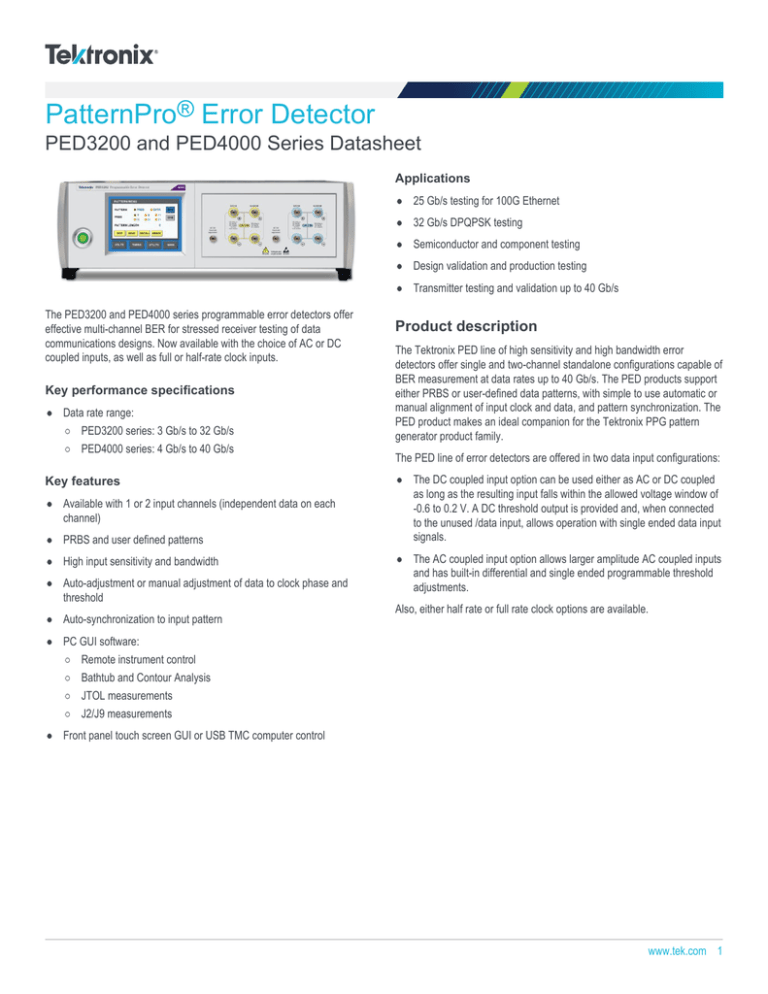
The PED3200 and PED4000 series programmable error detectors offer
effective multi-channel BER for stressed receiver testing of data
communications designs. Now available with the choice of AC or DC
coupled inputs, as well as full or half-rate clock inputs.
Key performance specifications
Data rate range:
PED3200 series: 3 Gb/s to 32 Gb/s
PED4000 series: 4 Gb/s to 40 Gb/s
Key features
Available with 1 or 2 input channels (independent data on each
channel)
PRBS and user defined patterns
High input sensitivity and bandwidth
Auto-adjustment or manual adjustment of data to clock phase and
threshold
Auto-synchronization to input pattern
Product description
The Tektronix PED line of high sensitivity and high bandwidth error
detectors offer single and two-channel standalone configurations capable of
BER measurement at data rates up to 40 Gb/s. The PED products support
either PRBS or user-defined data patterns, with simple to use automatic or
manual alignment of input clock and data, and pattern synchronization. The
PED product makes an ideal companion for the Tektronix PPG pattern
generator product family.
The PED line of error detectors are offered in two data input configurations:
The DC coupled input option can be used either as AC or DC coupled
as long as the resulting input falls within the allowed voltage window of
-0.6 to 0.2 V. A DC threshold output is provided and, when connected
to the unused /data input, allows operation with single ended data input
signals.
The AC coupled input option allows larger amplitude AC coupled inputs
and has built-in differential and single ended programmable threshold
adjustments.
Also, either half rate or full rate clock options are available.
PC GUI software:
Remote instrument control
Bathtub and Contour Analysis
JTOL measurements
J2/J9 measurements
Front panel touch screen GUI or USB TMC computer control
www.tek.com 1
Datasheet
100G Ethernet four lane end-to-end test using PED3200 series error detector and PPG3000 series pattern generator
Specifications
All specifications are guaranteed unless noted otherwise. All specifications apply to all models unless noted otherwise.
Data input
Data rate
Range (PED3200)
3 Gb/s to 32 Gb/s
Range (PED4000)
4 Gb/s to 40 Gb/s
DC coupled input option
Ground referenced CML like input. AC coupled data input permitted within allowed voltage window.
Differential amplitude
25 mV to 1.0 Vp-p
Single-ended amplitude
25 mV to 750 mVp-p
Voltage window
-0.6 V to +0.2 V
Termination voltage
0.0 V
Input impedance
50 Ω
Connector
2.4 mm
AC coupled input option
Differential amplitude
AC coupled input with broadband bias tees featuring a 3 dB bandwidth of 10 kHz to >50 GHz.
6 mV to 1.0 Vp-p
Single-ended amplitude
6 mV to 750 mVp-p
Termination voltage
0.0 V
Input impedance
50 Ω
Connector
2.4 mm
ESD sensitivity
2 www.tek.com
250 V, Human body model (HBM)
PED3200 And PED4000 Datasheet
Threshold output
Output voltage
Range
DC voltage terminated 50 Ω to ground
-0.5 V to 0.125 V
Sampling point set points
Eye edge BER threshold
Range
1e-1 to 1e-11
Resolution
1e-1
Sync BER threshold
Range
1e-1 to 1e-8
Resolution
1e-1
Full rate clock input option
Amplitude
Differential range
AC coupled, full rate
300 mVP-P to 1.0 VP-P
Single-ended range
300 mVP-P to 1.0 VP-P
Connector
2.4 mm
Clock to data phase adjustment
100 ps (-50 ps to +50 ps)
ESD sensitivity
1000 V, Human body model (HBM)
Half rate clock input option
Amplitude
AC coupled, half rate
Differential range
300 mVP-P to 1.0 VP-P
Single-ended range
300 mVP-P to 1.0 VP-P
Connector
2.4 mm
Clock to data phase adjustment
100 ps (-50 ps to +50 ps)
ESD sensitivity
1000 V, Human body model (HBM)
Data patterns
Pattern type
Data (from memory) or PRBS.
Length and type are individually settable on each channel.
PRBS pattern lengths
27 -1 bits
Polynomial = X7 + X6 + 1
29 - 1 bits
Polynomial = X9 + X5 + 1
211
Polynomial = X11 + X9 + 1
- 1 bits
215 - 1 bits
Polynomial = X15 + X14 + 1
223
- 1 bits
Polynomial = X23 + X18 + 1
231 - 1 bits
Polynomial = X31 + X28 + 1
www.tek.com 3
Datasheet
Data patterns
User-defined pattern depth
Number of channels
Single bit pattern resolution
1 channel
4 Mbit
2 channels
2 Mbit
Mechanical
Front panel width (with mounting
tabs)
48.3 cm (19.0 in)
Height
13.3 cm (5.25 in)
Width
45.1 cm (17.75 in)
Depth (rack mount)
34.3 cm (13.5 in)
Weight (1 channel)
11.1 kg (24.5 lbs)
Operating temperature
0 °C to 40 °C (32 °F to 104 °F)
Ordering information
Models
PED3201
32 Gb/s Programmable error detector, 1 channel
PED3202
32 Gb/s Programmable error detector, 2 channels
PED4001
40 Gb/s Programmable error detector, 1 channel
PED4002
40 Gb/s Programmable error detector, 2 channels
Options
Instrument options
PED3201 AC
AC coupled input option for PED3201
PED3201 DC
DC coupled input option for PED3201
PED3201 HCLK
Half rate clock input option for PED3201
PED3201 FLCLK
Full rate clock input option for PED3201
PED3202 AC
AC coupled input option for PED3202
PED3202 DC
DC coupled input option for PED3202
PED3202 HCLK
Half rate clock input option for PED3202
PED3202 FLCLK
Full rate clock input option for PED3202
PED4001 AC
AC coupled input option for PED4001
PED4001 DC
DC coupled input option for PED4001
PED4001 HCLK
Half rate clock input option for PED4001
PED4001 FLCLK
Full rate clock input option for PED4001
4 www.tek.com
PED3200 And PED4000 Datasheet
PED4002 AC
AC coupled input option for PED4002
PED4002 DC
DC coupled input option for PED4002
PED4002 HCLK
Half rate clock input option for PED4002
PED4002 FLCLK
Full rate clock input option for PED4002
Power plug options
Opt. A0
North America power plug (115 V, 60 Hz)
Opt. A1
Universal Euro power plug (220 V, 50 Hz)
Opt. A2
United Kingdom power plug (240 V, 50 Hz)
Opt. A6
Japan power plug (100 V, 50/60 Hz)
Opt. A10
China power plug (50 Hz)
Opt. A11
India power plug (50 Hz)
Opt. A99
No power cord
Manuals
071-3413-xx
Printed PPG/PED Installation & Safety Instructions
077-1095-xx
PED3200/PED4000 Series Programmable Error Detector User Manual, PDF-only, downloadable from Tektronix.com
PC Software GUI and Analysis Tool
25 Gb/s and 32 Gb/s NRZ Signal Contour Analysis
A PC-based software tool for remotely controlling the instrument, gathering and saving data (such as, bathtub and contour plots), and performing data systems analysis (J2/J9
and JTOL measurements) is available for use with both PED3200 and PED4000 error detectors. The tool is an executable file and is available upon request from Tektronix.
www.tek.com 5
Datasheet
14 Gb/s and 25 Gb/s PAM4 Signal Contour Analysis
Tektronix is registered to ISO 9001 and ISO 14001 by SRI Quality System Registrar.
Product(s) complies with IEEE Standard 488.1-1987, RS-232-C, and with Tektronix Standard Codes and Formats.
ASEAN / Australasia (65) 6356 3900
Belgium 00800 2255 4835*
Central East Europe and the Baltics +41 52 675 3777
Finland +41 52 675 3777
Hong Kong 400 820 5835
Japan 81 (3) 6714 3010
Middle East, Asia, and North Africa +41 52 675 3777
People's Republic of China 400 820 5835
Republic of Korea +822 6917 5084, 822 6917 5080
Spain 00800 2255 4835*
Taiwan 886 (2) 2656 6688
Austria 00800 2255 4835*
Brazil +55 (11) 3759 7627
Central Europe & Greece +41 52 675 3777
France 00800 2255 4835*
India 000 800 650 1835
Luxembourg +41 52 675 3777
The Netherlands 00800 2255 4835*
Poland +41 52 675 3777
Russia & CIS +7 (495) 6647564
Sweden 00800 2255 4835*
United Kingdom & Ireland 00800 2255 4835*
Balkans, Israel, South Africa and other ISE Countries +41 52 675 3777
Canada 1 800 833 9200
Denmark +45 80 88 1401
Germany 00800 2255 4835*
Italy 00800 2255 4835*
Mexico, Central/South America & Caribbean 52 (55) 56 04 50 90
Norway 800 16098
Portugal 80 08 12370
South Africa +41 52 675 3777
Switzerland 00800 2255 4835*
USA 1 800 833 9200
* European toll-free number. If not accessible, call: +41 52 675 3777
For Further Information. Tektronix maintains a comprehensive, constantly expanding collection of application notes, technical briefs and other resources to help engineers working on the cutting edge of technology. Please visit www.tek.com.
Copyright © Tektronix, Inc. All rights reserved. Tektronix products are covered by U.S. and foreign patents, issued and pending. Information in this publication supersedes that in all previously published material. Specification and
price change privileges reserved. TEKTRONIX and TEK are registered trademarks of Tektronix, Inc. All other trade names referenced are the service marks, trademarks, or registered trademarks of their respective companies.
29 Jan 2016
www.tek.com
65W-28638-5

