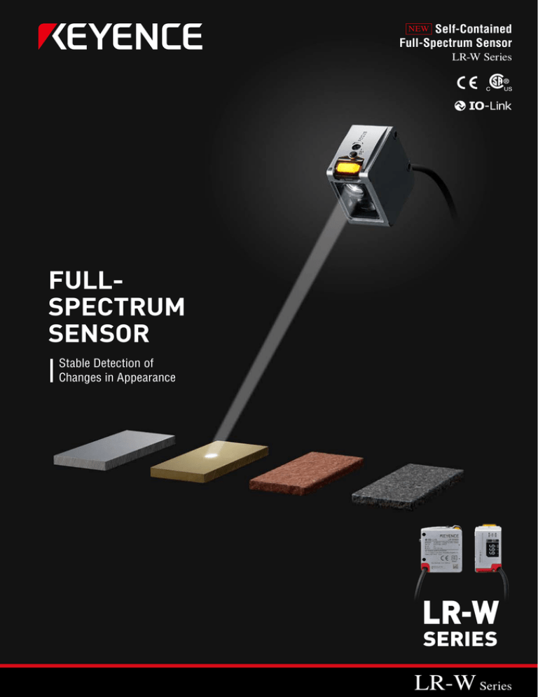
Self-Contained
Full-Spectrum Sensor
NEW
LR-W Series
FULLSPECTRUM
SENSOR
Stable Detection of
Changes in Appearance
LR-W
SERIES
LR-W Series
PRESENCE AND ABSENCE
Part detection in a mould or die
Rounded target detection on a moving conveyor
WHAT IS
A FULL-SPECTRUM
SENSOR?
A Full-Spectrum sensor features unmatched detecting
capabilities that allow it to complete the simplest to the
most complex applications with ease. The LR-W Series is
one such sensor that can truly handle the Full-Spectrum of
applications.
Product differentiation based on appearance
Product treatment/coating verification
PRODUCT DIFFERENTIATION
2
REGISTRATION MARKS
Registration mark detection on film
Registration mark detection on a rounded surface
White LED
NEW
Adjustable Beam Spot
Self-Contained
Full-Spectrum Sensor
LR-W Series
Confirming proper colour shade
Range Up To 500 mm
Differentiating very similar colours
COLOUR VERIFICATION
3
4
UNMATCHED
DETECTION CAPABILITIES
Superior Full-Spectrum Detecting Capabilities
500 mm Range with Adjustable Beam Spot
Automatic Light Power Control for Stable Detection
EASE-OF-USE
One Touch Calibration
User-Friendly Display
Easy Integration Into Any Setup
DURABILITY
Robust Metal Housing
Water Resistant
Dustproof
5
UNMATCHED DETECTING CAPABILITIES
Full-Spectrum Detection
WHITE LED
RED LED
Unlike conventional sensors which only
use a Red LED, the LR-W utilises a White
LED and the full colour spectrum. By
doing this, the LR-W can reliably and
stably differentiate a much wider range
of targets.
Spectrum of Light
Examples of targets the LR-W can stably detect
Targets with
Slight Colour Changes
Metal Targets
Tilted Targets
High Power White LED and Automatic Power Control
By utilising a High Powered White LED, the
LR-W ensures detection of dark targets.
For glossy targets, the LR-W features
an Automatic Power Control function
that optimises the sensor's power and
sensitivity to ensure stable detection.
Detecting Dark Targets
Detecting Glossy Targets
500,000× High Dynamic Range
6
*10 ms or slower response time is required for
Automatic Power Control
Superior Detecting Distance with Adjustable Spot
Minimum
spot
3.5 mm
30 mm
9 mm
100 mm
Easy Spot
Adjustment
18 mm
250 mm
500 mm
500 mm
Detecting
Range
With an impressive 500 mm range, the LR-W is able to solve applications that were once considered out of reach. The LR-W also
features an easy to adjust spot that can be widened or focused to provide the best detection based on the target. These two features
combine to make the LR-W a truly all-purpose solution.
Auto Tuning Ensures Best Detection Method
AUTO TUNING
COLOUR
COLOUR + INTENSITY
Colour
Brightness
Surface Finish
By using the Auto Tuning function, the LR-W accounts for a target's colour, brightness, and surface finish to determine which
detection method is best suited for the given application. This helps to ensure stable detection regardless of target variations.
7
EASE-OF-USE
Simplified Calibration
The LR-W can easily perform three
different types of calibration. Users
can choose from One-Point
(1-P), Two Point (2-P), and Master
Calibration.
Product Differentiation
1-P Calibration
Registration Mark Detection
AUTO TUNING
One simple press is all that is needed to
stably match a specific product.
2-P Calibration
Detect difficult registration marks with a
simple Two-Point (2-P) Calibration.
Varying Colour Detection
Master Calibration
Innovative tuning option to set clear
thresholds for target variation.
Master Calibration/
Master Addition Calibration
Products fluttering on conveyor belts
8
Color variances within products
Colour inconsistencies, vibration, worn surfaces, and tilting or
angling of targets can all lead to unstable detection. Master
Calibration allows user's to teach the sensor these variations in
advance. Master Addition Calibration enables conditions to be
easily added as they arise.
Intuitive Display and Indicators
Clear Display
Highly Visible
Indicator
The LR-W features a highly visible 7-segment display that
provides constant feedback, as well as indicators to show
detection mode and stability.
The highly visible indicator is bright and can clearly be seen
from long distances.
Seamless Integration
Bipolar Outputs
NPN
M12 Quick
Disconnect
PNP
Same model
NPN/PNP switching output
The LR-W has selectable NPN or PNP outputs in the same
unit, making it easy to standardise on different machine types.
Standard Mounting Holes
The LR-W Series offers a standard M12 4-pin quick disconnect
option for easy wiring.
Adjustable
Brackets
25.4 mm
The LR-W features a standard mounting pitch of 25.4 mm,
allowing it to easily mount on existing brackets.
If flexible mounting is required, an adjustable mounting
bracket is also available.
9
DURABILITY
High Environmental Resistance
Washdown
Resistant
The LR-W Series meets the requirements of IP65 and IP67
for areas requiring washdown.
Dust and
Dirt Resistant
These IP Ratings also allow the LR-W to perform in dusty or
dirty environments.
Robust Housing
Die Cast Metal
Housing
The die cast metal housing can withstand impact from
products, tools, or workers.
10
Secure
Mounting
The rigid metal housing of the LR-W allows for secure
mounting without the fear of damage to the unit.
MU-N
Series
Multi-Sensor
Controller
The LR-W Series can be connected
to the MU-N to allow for increased
functionality.
Various Output Options
1 Output (16 banks)
Selectable
I/O
Rich OLED Display
Value at ON
Peak during ON
Parallel 4 Outputs (2 banks)
Binary 15 Outputs (No bank)
Analogue
4 to 20 mA or 0 to 10 V
The MU-N Series controller offers customisable I/O.
This includes both control outputs and a voltage/
current analogue output.
The combination of an OLED and 7-Segment Display
allow users to quickly view data in real time. The MU-N
also has the ability to display live graphs for easy
machine monitoring.
Network Compatibility
Settings Back-Up Function
Backs up setting
information
Enable copying and
writing of data via
wide varieties of
communication
protocols.
By pairing the MU-N Series with the KEYENCE NU Series,
users can transmit data over a standard industrial
network. Compatible networks include EtherNet/IP™,
EtherCAT, and PROFINET.
Sensor Replacement
Copies the setting to a
new sensor
The Settings Back-Up Function allows users to save
sensor settings on the MU-N and quickly transfer them
to new sensors that are attached.
11
Related Products
LR-Z Series
Part presence
regardless of
varying colours
LR-T Series
Welding cell
target detection
When colour/
contrast needs
to be ignored
LR-T Series
Metal level
detection
Distance-based measuring principles
enable stable presence detection of any
object.
LR-Z
SERIES
CMOS Laser Sensors
LR-Z
Detecting Distance [35 to 250 mm]
Best in class detecting ability
Transparent object detection
Stainless steel body with IP69K rating
LR-T
SERIES
TOF Laser Sensors
LR-T
Detecting Distance [0.06 to 5 m]
Max. 5 m detecting distance
Custom IC for superior detecting capabilities
Metal body with IP65/IP67 enclosure rating
12
Lineup
Type
Detecting distance
Min. spot diameter
Light source
Cable
(2 m)
Model
Weight
LR-W500
Approx.
170 g
LR-W500C
Approx.
110 g
Model
Material / weight
LR-WA1*1 *2
SUS304,
PMMA,
etc.
Approx.
5g
Adjustable spot
●
Approx. ø3.5 mm
(at detecting distance of 100 mm)
White LED
Approx. ø9 mm
(at detecting distance of 250 mm)
●
30 to 500 mm
Approx. ø18 mm
(at detecting distance of 500 mm)
●
M12 connector
(Cable sold
separately)
Mounting bracket
Type
Attachment
Model
Material / weight
OP-88021*1
SUS304
Approx.
110 g
Adjustable bracket
for LR-W Series
(M3 screw × 2 supplied)
OP-88023
Zinc nickel plating,
etc.
Approx.
110 g
Adjustable bracket
locking screw
(105 mm)
OP-88024
Iron nickel plating
Approx.
140 g
Standard
mounting bracket
for LR-W Series
(M3 screw × 2 supplied)
Type
Lustre
canceling
attachment
*1 When using LR-WA1, detecting range may decrease on targets with low reflectance.
Perform sufficient checks in the actual installation environment.
*2 When using the LR-WA1, the enclosure rating (IP65/IP67) is not met.
*1 The 4-pin M12 connector type may not be mounted in the orientation shown in the picture (connector
downward). Confirm the dimensions and surroundings carefully.
Cable
Appearance
Cable material
Sensor side
Cable end
Cable:
PVC (Polyvinyl chloride)
M12 4-pin
straight
Cable:
PUR (Polyurethane)
Length (m)
Model
Weight
2
OP-75721
Approx. 60 g
5
OP-87272
Approx. 125 g
10
OP-85502
Approx. 230 g
2
OP-87636
Approx. 75 g
10
OP-87637
Approx. 330 g
2
OP-75722
Approx. 65 g
5
OP-87273
Approx. 130 g
10
OP-87274
Approx. 235 g
2
OP-87640
Approx. 75 g
10
OP-87641
Approx. 330 g
Loose wires
Cable:
PVC (Polyvinyl chloride)
M12 4-pin
L-shape
Cable:
PUR (Polyurethane)
13
Controller
Type
Control output
External input
Main unit
4 standard outputs max.
(15 outputs available using
binary logic)
Analogue output
Model
Weight
1 output max.
(control output / external input
selectable)
MU-N11
Approx. 70 g
—
MU-N12
Approx. 70 g
5 inputs max.
(three of the five inputs can be
switched to control outputs)
Expansion unit
Power supply cable for MU-N Series
Appearance
Applicable unit
Cable material
Cable end
Controller side
Length (m)
Model
Weight
MU-CB8
Approx. 150 g
MU-CB4
Approx. 120 g
MU-CB6
Approx. 130 g
MU-CB2
Approx. 100 g
0.3
MU-CC4
Approx. 30 g
Length (m)
Model
Weight
2
OP-88025
Approx. 75 g
10
OP-88026*1
Approx. 280 g
2
OP-88027
Approx. 75 g
10
OP-88028*1
Approx. 280 g
8-core loose wires
Main unit
4-core loose wires
2
6-core loose wires
Expansion unit
PVC (Polyvinyl chloride)
2-core loose wires
Connector
M12 4-pin
straight
Main unit
Cable is not included with the controller. Please purchase it separately.
Sensor-to-controller cable (for 4-pin M12 connector type)
Appearance
Cable material
Sensor side
Controller side
M12 4-pin
straight
PVC (Polyvinyl chloride)
Connector
M12 4-pin
L-shape
*1 The 10 m cable includes one spare connector for the controller side.
Connector set for sensor-to-controller connection
Appearance
Type
For PVC (Polyvinyl chloride) cable
For PUR (Polyurethane) cable
Applicable model
Model
Weight
LR-W500
OP-75721 / 87272 / 85502
OP-75722 / 87273 / 87274
OP-88029
Approx. 3 g
OP-87636 / 87637
OP-87640 / 87641
OP-88030
Approx. 3 g
This set is required when the sensor cable end is loose wire or when the sensor-to-controller cable is cut.
Controller mounting options
Appearance
14
Type
Description
Model
Weight
Mounting adapter (for main unit)
Allows the main unit to be mounted without a
DIN rail.
OP-76877
Approx. 11 g
End unit (for expansion)
Used to secure the main and expansion units
to DIN rail from both ends.
End units must be used when an expansion
unit is connected. (2 pieces included)
OP-26751
Approx. 15 g
Sensor specifications
LR-W500
2 m cable type
Model
LR-W500C
M12 connector 4-pin type
Detecting distance
30 to 500 mm
Min. spot diameter
Adjustable spot
Approx. ø3.5 mm at 100 mm
Approx. ø9 mm at 250 mm
Approx. ø18 mm at 500 mm
Response time*1
Light source
Mutual interference reduction function
Timer
Power voltage
Power supply
Current consumption*2
200 μs / 1 ms / 10 ms / 100 ms / 500 ms selectable
White LED
Up to 2 units with alternate frequencies set
OFF / ON delay / OFF delay / One-shot
10 to 30 VDC, including 10% ripple (P-P), Class 2 or LPS
65 mA or less (without load) at 24 VDC;
120 mA or less (without load) at 12 VDC
Control output
NPN open collector / PNP open collector selectable
30 VDC or less, 50 mA or less, remaining voltage: 2 V or less
N.O. / N.C. selectable
External input
Tuning / laser emission stop selectable
Short circuit current: 1 mA or less for NPN / 2 mA or less for PNP
For the applied voltage, see the wiring diagrams in the instruction manual.
For the input times, see the time charts in the instruction manual.
I/O*3
Protection circuit
Protection against reverse power connection, power supply surge, output overcurrent, output surge, and reverse output connection
IP65 / IP67 (IEC60529)
Incandescent lamp: 10000 lux or less, Sunlight: 20000 lux or less
-20 to +50°C (no freezing)
35 to 85%RH (no condensation)
1000 m/s2 in X, Y, Z axis directions respectively 6 times
10 to 55 Hz Double amplitude 1.5 mm in the X, Y, Z axis directions respectively, 2 hours
Enclosure rating
Ambient light
Ambient temperature
Ambient humidity
Shock resistance
Vibration resistance
Environmental
resistance
Case : Zinc die cast (Nickel chrome plating), Indicator cover: PPSU, Buttons: PES
Lens cover and display : PMMA (scratch-resistant coating), Cable bushing : PBT
Cable (2 m cable type only) : PVC, Spot adjustment dial: Iron (triiron tetraoxide coated)
Connector ring (4-pin M12 connector type only): PMP, Connector socket (4-pin M12 connector type only) : PEI
Material
Weight
Approx. 170 g (including cable)
Approx. 110 g
*1 When alternate frequencies are set, the response time increases by approximately 20%. *2 195 mA or less (at 10 V, with load)
*3 IO-Link : Specification v.1.1/COM2 (38.4 kbps) is supported. The setup file can be downloaded from KEYENCE website (http://www.keyence.com).
If you are using the product in an environment in which you cannot download files over the Internet, contact your nearest KEYENCE office.
Reference data of distance vs.
spot diameter (Typical)
Spot
diameter
(mm)
50
45
40
35
30
Focused at 100 mm
25
Focused at 200 mm
20
Focused at 300 mm
15
Focused at 400 mm
10
Focused at 500 mm
5
Reference for minimum spot diameter
0
Distance
0
50
100
150
200
250
300
350
400
450
500 (mm)
I/O circuit Diagrams
Control output circuit
Input circuit
When NPN is selected
When NPN is selected
➂ Blue
Main circuit
➃ Black
0V
When PNP is selected
➂Blue
PLC, etc.
0V
Main circuit
➃Black
➂Blue
➀Brown
10 to 30 VDC
Load
Overcurrent
protection circuit
10 to 30 VDC
➁White
When PNP is selected
➀Brown
Main circuit
➀Brown
10 to 30 VDC
Load
Overcurrent
protection circuit
Main circuit
➀ Brown
0V
10 to 30 VDC
M12 Connector
pin layout
PLC, etc.
2
➁White
➂Blue
1
3
0V
4
15
Controller specifications
MU-N11
Main unit
Model
Single output : 300 μs / 1.1 ms / 11 ms / 100 ms / 500 ms selectable
Multiple output : 2 ms / 3 ms / 11 ms / 100 ms / 500 ms selectable
Up to 2 units with alternate frequencies set
OFF /OFF delay / ON delay / One-shot
24 VDC, ripple (P-P) 10% or less, Class 2 or LPS
135 mA or less (without load)*1
120 mA or less (without load)*2
Response time
Mutual interference reduction function
Timer
Power voltage
Power supply
Current consumption
I/O
Control output
4 outputs max.
NPN open collector / PNP open collector selectable
24 VDC or less, main unit : 50 mA or less*3, expansion unit : 20 mA or less
Remaining voltage: 2 V or less
N.O. / N.C. selectable
External input
5 inputs max. (three of the five inputs can be switched to control outputs)
Short circuit current : 1 mA or less for NPN / 2 mA or less for PNP
For the applied voltage, see the wiring diagrams in the instruction manual.
1 output max. (control output / external input selectable)
Current output/voltage output selectable
Current output : 4 to 20 mA
Maximum load resistance : 450 Ω
Voltage output : 0 to 10 V
External load resistance : 5 kΩ or more
Analogue output
Protection circuit
Unit expansion
Environmental resistance
MU-N12
Expansion unit
—
Protection against reverse power connection, power supply surge, output overcurrent, output surge, and reverse output connection
Up to 4 units per main unit*4
-20 to +50°C (no freezing)
35 to 85%RH (no condensation)
1000 m / s2 in X, Y, Z axis directions respectively 6 times
10 to 55 Hz Double amplitude 1.5 mm in the X, Y, Z axis directions respectively, 2 hours
Case and dust cover : Polycarbonate, Button : Polyacetal, Display panel : Acrylic
Approx. 70 g
Ambient temperature
Ambient humidity
Shock resistance
Vibration resistance
Material
Weight
*1 335 mA or less (when 4 outputs are used, with load) *2 200 mA or less (when 4 outputs are used, with load) *3 20 mA or less when an expansion unit is connected.
*4 Contact KEYENCE in cases of expansion using models other than the sensor amplifiers supporting N-bus (generic name for KEYENCE's simplified wiring system) including the MU-N Series and the NU Series communication unit.
I/O circuit diagrams
Control output circuit
Input circuit
When NPN is selected
When NPN is selected
Main circuit
Main circuit
Blue*(➂)
Analogue current /
voltage output circuit
White (➁)
(When analogue output is selected)
24 VDC
Black(➃)/White(➁)/
Orange/Grey
(When control output is selected)
Blue*(➂)
Brown*(➀)
0V
Blue(➂)
0V
When PNP is selected
Load
Main circuit
White (➁)/Orange/
Grey/ Pink/Purple
(When external input is selected)
Analogue input device
0V
Brown*(➀)
Overcurrent protection circuit
24 VDC
PLC,
etc.
When PNP is selected
16
Brown(➀)
24 VDC
Load
Black(➃)/White(➁)/
Orange/Grey
(When control output is selected)
Blue*(➂)
* MU-N11 only
Brown*(➀)
24 VDC
24 VDC
Pin layout
when the M12 connector (4-pin)
cable is used
2
PLC, etc.
Main circuit
Main circuit
Overcurrent protection circuit
Brown*(➀)
Analogue output circuit *
1
3
4
White (➁)/Orange/
Grey/Pink/Purple
(When external input is selected)
Blue*(➂)
0V
0V
Dimensions
Unit: mm
Dial
LR-W500
Button
11.4
11
Indicator
13
18.5
1.6
38.1
24.6
11
35.3
11.25
5.35
1.6
Centre of
emitted light
Button
Button
STB C I
25.4
46.7
45.2
32.2
28.7
14.9
Display
13.3
45°
Centre of
received light
°
135
Reference surface
for detecting distance
ø4.0, 4-core × Brown/
Blue/Black/White 0.20 mm2
Cable length: 2 m
45°
90
°
2 × ø3.2
33.8
Dial
LR-W500C
Button
11
11.4
Indicator
13
18.5
24.6
38.1
11
35.3
5.35
1.6
Centre of
emitted light
Button
Button
25.4
STB C I
46.7
28.7
11.25
1.6
45.2
32.2
14.9
Display
13.3
Centre of
received light
12.5
Reference surface
for detecting distance
2 × ø3.2
M12 connector
Pin layout
2
15.6
1
3
28.4
4
17
Dimensions
OP-88021
OP-88021 + LR-W500
Angle non-adjustable area when OP-88021 is used
52
4.5
4.5
ø6.3
9
7
Centre of emitted light
0.6
Reference surface for detecting distance
39
20
ø
(50°)
Centre of emitted light
67
62.8
(33.4) 25.4
42
Rotational centre of
main body
Non-adjustable
area
Non-adjustable area
Non-adjustable
area
42
°
4
29
R
2-
16
36°
30.9
44.7
°
36°
Non-adjustable area
(4-R1.75)
29
°
29
Centre of received light
°
3.5
.9
2
2 -R
14° 14°
36°
4.5
6 9 11 11 9
3.5
2-R
52.6
36
5)
2.2
-R
(6
26.5
12.5
29
°
2-M3 × 0.5
25
SUS304
Plate thickness: 3
6.1
(50°)
45.9
SUS304
Plate thickness: 3
OP-88023
OP-88023 + LR-W500
Hexagon socket head cap screw
(M5, Length: 15 mm,
Across flats: 4 mm,
Iron nickel plating)
36.9
19.5
35.8
4×M3 P=0.5
ø20.1, ø24
spot facing
depth: 1.8
25.4
17.9
17.9
22.6 Reference surface for
detecting distance
23.7
17.9
25.4
3.2
ø27 17.4
ø22
OP-88023 + OP-88024 + LR-W500
22.6
23.7
23.7
Centre of emitted light
18.2
Nut (M5, Iron nickel plating)
Reference surface for
detecting distance
Centre of
emitted light
4.8
20.8
SUS304
2.7
20.8
11.1
26
2.7
Centre of
received light
11.1
26
Centre of
received light
12.5
3.3
12.5
4.4 Zinc nickel plating
29.1
19.5
OP-88024
LR-WA1 + LR-W500
42.7
12.5
3.3
19.5
When OP-88023 + OP-88024 + LR-W500C
+ L-shape type M12 connector are used
24.2
(40)
(24.6)
M12 × P1.75
3.3
When mounting the unit as shown
in the figure below (connector
downward), carefully check the
surroundings for any objects that
might interfere with the connector
cable.
5
3.
R2
Reference surface for
detecting distance
42.7
Warning for when an
M12 connector type is used
Rotational centre
of main body
2 × ø24, thickness: 2.5
29.1
ø12
Centre of emitted light
Centre of received light
105
64.7
1.3
11
3.3
(38.1)
33.7
33.7
R2
15.2
13
3.5
64.7
16.8
14.9
Iron nickel plating
18
31.8
(48.1) 45
)
28.7
(R73.9
Across flats: 18,
thickness: 10
Unit: mm
MU-N11 (Main unit)
MU-N12 (Expansion unit)
28
28
Maximum when
cover is open:
108
MAX.
135°
Maximum when
cover is open:
108
MAX.
135°
(41.9) 36.9
(41.9) 36.9
15.8
15.8
16
28
19.5
23.7
16
28
35.4
19.5
23.7
21
78.4
35.4
21
78.4
PVC: 8.9 min.
PVC: 8.9 min.
PUR: 28.2 min.
PUR: 28.2 min.
15.5 min.
15.5 min.
When mounting adapter is attached (OP-76877, optional, sold separately)
When the communication unit is connected without using a power supply cable
28
18.8
19
5
27.2
Maximum when
cover is open:
108
2 × ø3.4
34
15
MAX.
135°
(41.9) 36.9
2×(4.4 × 3.4)
24
22
15.8
28
19.5
15
23.7
35.4
78.4
28.6
35
8.2
PVC: 8.9 min.
Back of mounting adapter
PUR: 28.2 min.
When expansion units are connected
End unit (OP-26751, optional, sold separately)
6
End unit
End unit
*1
When mounted on a DIN rail
(22.6)
20.8
9.2
35.4
53.8
6
*1 End units must be used
when an expansion unit
is connected. (Optional)
L
No. of expansion units
1
2
3
4
5
6
L
28
56
84
112
140
19
■ Dimensions
Unit: mm
M12 connector cable for sensor
OP-75721 / 87272 / 85502
OP-75722/87273/87274
M12
43
OP-75721:2000/OP-87272:5000/OP-85502:10000
OP-75722:2000/OP-87273:5000/OP-87274:10000
33.8
ø14
M12
ø14
28.2
ø4.0 (4 × 0.20 mm2)
ø4.0 (4 × 0.20 mm2)
OP-87636 / 87637
OP-87640/87641
44
M12
OP-87636:2000/OP-87637 :10000
ø14.8
OP-87640 : 2000/ OP-87641 : 10000
8°
M12
27.4
ø14.8
34.5
ø4.7 (4 × 0.34 mm )
2
ø4.7 (4 × 0.34 mm2)
No.
Pin layout
1
2
4
3
➀
➁
➂
➃
Colour
Brown
White
Blue
Black
Power supply cable for MU-N
MU-CB8 / CB4 / CB6 / CB2
MU-CC4
2000
300
45
ø14
ø5.5 (4 × 0.35 mm2)
MU-CB8 :ø5.5 (8 × 0.35 mm2)
MU-CB4:ø5.5 (4 × 0.35 mm2)
MU-CB6:ø5.5 (6 × 0.35 mm2)
MU-CB2:ø5.5 (2 × 0.35 mm2)
M12
Colour
Brown
White
Blue
Black
No.
➀
➁
➂
➃
M12 Connector
pin layout
3
2
4
1
Sensor-to-controller cable (4-pin M12 connector type)
OP-88025 / 88026
OP-88027/88028
M12
43
OP-88025:2000/ OP-88026:10000
OP-88027:2000/ OP-88028:10000
33.8
ø14
M12
28.2
ø14
ø4.0 (4 × 0.20 mm2)
ø4.0 (4 × 0.20 mm2)
X
X
Y
2
➀
➁
➂
➃
➀
➁
➂
➃
M12 Connector pin layout
1
4
3
Colour
Brown
White
Blue
Black
Y
Connector pin layout
➀
➁
➂
➃
X
X
Y
2
➀
➁
➂
➃
➀
➁
➂
➃
M12 Connector pin layout
1
4
3
Colour
Brown
White
Blue
Black
Y
Connector pin layout
➀
➁
➂
➃
Warning for when an L-shape type
M12 connector is used
When the L-shape type M12 connector
is used, the cable is fixed in the
direction shown in the right figure. The
connector base cannot be rotated.
20
C A D D ATA D O W N L O A D
www.keyence.com/CADG
Network communication unit NU Series
Open field network unit
Type
Options
Appearance
Network
Model
EtherNet/IPTM
NU-EP1
Communication
unit
NU-EC1
EtherCAT
Dimensions
Model
Type
OP-51504
STP (Shielded twisted-pair) cable 0.2 m
OP-51505
STP (Shielded twisted-pair) cable 0.5 m
OP-51506
STP (Shielded twisted-pair) cable 1 m
OP-51507
STP (Shielded twisted-pair) cable 3 m
OP-51508
STP (Shielded twisted-pair) cable 5 m
OP-51509
STP (Shielded twisted-pair) cable 10 m
[➝P. 23]
NU-PN1
PROFINET
The NU Series models also have the following communication units: CC-Link-compatible NU-CL1 and DeviceNetTM-compatible NU-DN1.
EtherNet / IPTM compatible communication unit: NU-EP1
NU-EP1
Model
Compliant standards
IEEE802.3 (10BASE-T)
IEEE802.3u (100BASE-TX)
IEEE802.3af (Power over Ethernet, Class3)
Transmission rate
10 Mbps (10BASE-T)
100 Mbps (100BASE-TX)
Transmission media
STP or Category3 or higher UTP (10BASE-T)*1
STP or Category5 or higher UTP (100BASE-TX)
Maximum cable length
100 m (between this unit and Ethernet switch)
Ethernet specifications
Maximum number of
connectable hubs*2
Supported functions
EtherNet/IPTM specifications
Sensor connection
specifications
Power voltage
Power consumption
Weight (including connector)
Accessories
Number of connections
RPI (communication cycle)
4 (10BASE-T) 2 (100BASE-TX)
Cyclic communication
Message communication (Explicit message communication) supporting UCMM and Class 3
64
0.5 to 10000 ms (Unit: 0.5 ms)
Tolerable communication
bandwidth for cyclic
communication
6000 pps
Conformance test
Connectable sensor
Number of connectable sensors
Power supply
Allowable passing current*5
PoE power supply*6
Version A7 supported
N-bus sensor amplifier*3
16 units max.*4
Supplied from this unit via the sensor amplifier connector
1200 mA or less total
Supplied voltage: 24 V±10%, supplied current: 360 mA or less*7
24 VDC±10%, ripple (p-p) 10% or less (when the power supply connector is used)
48 VDC (57 VDC max.) (when PoE power supply is used)
1500 mW or less (60 mA or less at 24 V)*8
Approx. 80 g
Instruction manual, power supply connector, end unit × 2
* The following KEYENCE PoE power supply units cannot be connected: [DT-100A] [DT-500] [NE-V08]
*1 Use an STP cable or a Category5 or higher UTP cable for the connection using PoE power supply function.
*2 When a switch is used, there is no limit to the number of connectable units.
*3 N-bus is the name of KEYENCE's simplified wiring system for sensor amplifiers.
*4 Varies depending on the sensor amplifier to be connected.
*5 This is the current value that can be supplied to this unit or the sensor amplifier connected to this unit.
*6 This is the power that can be supplied to the sensor amplifier when the PoE power supply function is used.
*7 Varies depending on the ambient temperature. (-20 to +45°C: 360 mA or less, +45 to +50°C: 260 mA or less, +50 to +55°C: 140 mA or less)
*8 Excluding the current supplied to the connected sensor amplifier.
21
EtherCAT compatible communication unit: NU-EC1
NU-EC1
Model
Ethernet specifications
Compliant standards
Transmission rate
Transmission media
Distance between nodes
Communication port
EtherCAT communication
specifications
Supported functions
Sensor connection
specifications
Connectable sensor
Number of connectable sensors
Power supply
Allowable passing current*3
Power voltage
Power consumption
Weight (including connector)
Accessories
IEEE802.3u (100BASE-TX)
100 Mbps (100BASE-TX)
Category5e or higher STP
100 m
RJ-45 × 2
Process data object communication (cyclic communication)
Mailbox communication (message communication) CoE compatible
N-bus sensor amplifier*1
16 units max.*2
Supplied from the unit via a wiring-saving connector
1200 mA or less total
24 VDC ±10%, ripple (p-p) 10% or less
1700 mW or less (70 mA max. at 24 V)*4
Approx. 80 g
Instruction manual, power supply connector, end unit × 2
* EtherCAT is a registered trade name of BECKHOFF.
*1 N-bus is the name of KEYENCE's simplified wiring system for sensor amplifiers.
*2 Varies depending on the sensor amplifier to be connected.
*3 This is the current value that can be supplied to this unit or the sensor amplifier connected to this unit.
*4 Excluding the current supplied to the connected sensor amplifier.
PROFINET compatible communication unit: NU-PN1
Model
Ethernet specifications
Compliant Standards
Transmission rate
Transmission media
Maximum cable length
Maximum number of
connectable hubs
Supported functions
PROFINET specifications
Sensor connection
specifications
Power voltage
Power consumption
Weight
Accessories
Number of connectable controllers
Update Time
Version of GSDML
Conformance class
Conformance test
Applicable protocols
Connectable sensors
Number of connectable sensors
Power supply
Allowable passing current*2
PoE power supply*3
NU-PN1
IEEE802.3u (100BASE-TX)
100 Mbps (100BASE-TX)
STP or Category5 or higher UTP
100 m
2
Cyclic communication (Data I/O communication)
Acyclic communication (Record data communication)
1
2 to 512 ms
Version 2.3
Class A supported
V2.2.4 supported
LLDP, DCP
N-bus sensor amplifier*1
16 units max.*2
Supplied from this unit via the sensor amplifier connector
1200 mA or less total
Supplied voltage: 24 V±10%, supplied current: 360 mA or less*4
24 VDC±10%, ripple (p-p) 10% or less (when the power supply connector is used)
48 VDC (57 VDC max.) (when PoE power supply is used)
1500 mW or less (60 mA or less at 24 V)*5
Approx. 80 g
Instruction manual, power supply connector, end unit × 2
*1 N-bus is the name of KEYENCE's simplified wiring system for sensor amplifiers.
*2 Varies depending on the sensor amplifier to be connected.
*3 Indicates the current that can be supplied to the NU-PN1 and to the sensor units linked to the NU-PN1.
*4 This is the power that can be supplied to the sensor amplifier when the PoE power supply function is used.
*5 Varies depending on the ambient temperature. (-20 to +45°C: 360 mA or less, +45 to +50°C: 260 mA or less, +50 to +55°C: 140 mA or less)
*6 Excluding the current supplied to the connected sensor amplifier.
22
Dimensions
Unit: mm
NU-EP1/PN1
25.6
29.4
(42.5)
15
38.5
20.3
15
43.5
(0.2)
35.4
94.5
17.6
NU-EC1
15.8
22.2
15
29.4
170°
max.
1.9
34.1
Maximum when
the cover is opened
73.6
20.3
(38.5)
15
(0.2)
43.5
35.4
94.5
17.6
C A D D ATA D O W N L O A D
www.keyence.com/CADG
23
LR-W
SERIES
Self-Contained
Full-Spectrum Sensor
www.keyence.com
Copyright (c) 2015 KEYENCE CORPORATION. All rights reserved.
LRW_EU-WW-C-GB 1125-1 600H55 Printed in Japan

