Wire and Cable - 600 Volts and Below
advertisement
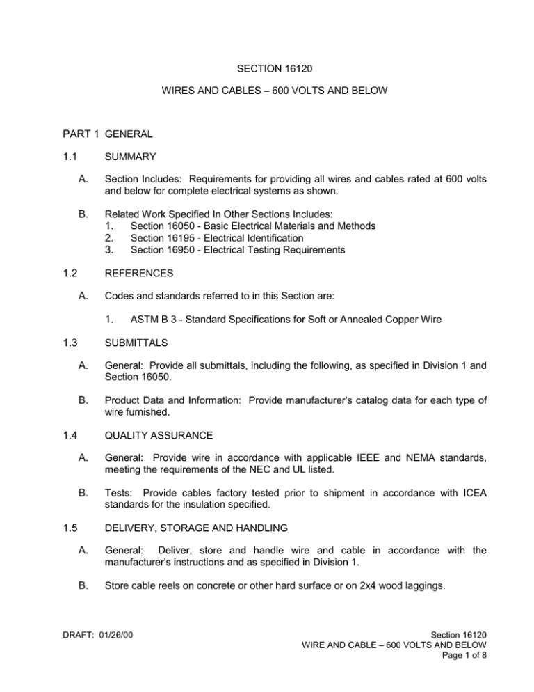
SECTION 16120 WIRES AND CABLES – 600 VOLTS AND BELOW PART 1 GENERAL 1.1 SUMMARY A. Section Includes: Requirements for providing all wires and cables rated at 600 volts and below for complete electrical systems as shown. B. Related Work Specified In Other Sections Includes: 1. Section 16050 - Basic Electrical Materials and Methods 2. Section 16195 - Electrical Identification 3. Section 16950 - Electrical Testing Requirements 1.2 REFERENCES A. Codes and standards referred to in this Section are: 1. 1.3 ASTM B 3 - Standard Specifications for Soft or Annealed Copper Wire SUBMITTALS A. General: Provide all submittals, including the following, as specified in Division 1 and Section 16050. B. Product Data and Information: Provide manufacturer's catalog data for each type of wire furnished. 1.4 QUALITY ASSURANCE A. General: Provide wire in accordance with applicable IEEE and NEMA standards, meeting the requirements of the NEC and UL listed. B. Tests: Provide cables factory tested prior to shipment in accordance with ICEA standards for the insulation specified. 1.5 DELIVERY, STORAGE AND HANDLING A. General: Deliver, store and handle wire and cable in accordance with the manufacturer's instructions and as specified in Division 1. B. Store cable reels on concrete or other hard surface or on 2x4 wood laggings. DRAFT: 01/26/00 Section 16120 WIRE AND CABLE – 600 VOLTS AND BELOW Page 1 of 8 PART 2 PRODUCTS 2.1 MANUFACTURERS A. Acceptable manufacturers are listed below. products may be submitted. 1. Wire and Cable a. b. c. 2. Thomas & Betts 3M Ideal Color Coding Marker a. b. 2.2 Okonite Rome Southwire Wire Connectors a. b. c. 5. Belden Dekoron Okonite Multiconductor Cable a. b. c. 4. American Southwire Rome Instrumentation Cable a. b. c. 3. Other manufacturers of equivalent Brady Thomas & Betts MATERIALS A. Conductors: Provide soft drawn or annealed copper conductors with 98 percent minimum conductivity, meeting requirements of ASTM B 3. Use stranded conductors except solid No. 12 and No. 10 AWG may be used in lighting fixture and convenience outlet wiring. B. Insulation: Provide wires and cables with insulation as follows: 1. Power, control and lighting wiring DRAFT: 01/26/00 Section 16120 WIRE AND CABLE – 600 VOLTS AND BELOW Page 2 of 8 a. b. 2. NEC Type Letter Insulation Material Nos. 14, 12 and 10 AWG XHHW Cross-linked Polyethylene No. 8 AWG and Larger RHW Cross-linked Polyethylene Multiconductor Cables: Insulate individual conductors with 15 mils of polyethylene or PVC and 4 mil nylon jacket. Cable wrap the cable conductor with type binder and an outer jacket not less than 45 mils of PVC. Use ICEA Method 1 for color coding wires. a. Two conductor or single pair: Stranded No. 16 AWG wire, 600 volt polyethylene insulation, tinned copper drain wire, overlapped metalized tape overall shield providing 100 percent shield coverage and outer jacket of PVC. Belden Cat. No. 8719. b. Three Conductor: Stranded No. 16 wire, 600 volt polyethylene insulation, tinned copper drain wire, overlapped metalized tape overall shield providing 100 percent shield coverage and outer jacket of PVC. Belden Cat. No. 8618. Multiple Pairs or Triads: Provide individually shielded pairs or triad of stranded No. 16 AWG wire with overall shield. Insulate each wire for 600 volts with 15 mils of PVC and a 4 mil nylon jacket. Assemble pairs or triads with tinned copper drain wire and metalized tape shield providing 100 percent shield coverage. Cable pair or triad together with tinned copper drain wire and overall metalized tap shield. Printed Data on Covering: Use wire and cable with the following information surface printed at regular intervals throughout the entire length. 1. 2. 3. 4. 2.3 Conductor Size Instrumentation Wiring: The use of manufacturers name and catalog number is for the purpose of establishing quality and general configuration designed. c. C. Single Conductor: Provide insulation as follows: Manufacturer or trade name. Size of conductor. Type of insulation. Voltage classification. WIRE CONNECTIONS AND CONNECTING DEVICES A. Connectors for No. 10 AWG and Smaller: connectors. DRAFT: 01/26/00 Use insulated compression type butt Section 16120 WIRE AND CABLE – 600 VOLTS AND BELOW Page 3 of 8 B. Connectors for No. 8 AWG and Larger: Use UL, Inc. listed compression type tube connectors for parallel or butt splices. Provide companion preformed plastic insulating covers or tape to provide insulation equal to conductor insulation. C. Miscellaneous Connectors: Use preinsulated spring connectors for lighting and receptacle splices and pigtails. D. Solderless Lugs: Provide solderless terminal lugs for stranded and multiple solid conductors at connection to terminals or use UL listed crimp tool compression style lugs. E. Control Wire Terminations: Provide spade lug or pressure type control conductor connection terminations for control wiring terminations. Make lug bolting at devices or bus bars with a flat washer, a Belleville washer and a locknut. 2.4 COLOR CODING A. Use a vinyl impregnated cloth tape resistant to oil, dirt and heat for conductor color coding. PART 3 EXECUTION 3.1 INSTALLATION A. General: Swab new and existing conduits to be used to clear debris and remove moisture before conductor installation. Install conductors in raceways with no splices between boxes. B. Pulling Equipment: Pull conductors using proper equipment without exceeding manufacturer's recommendation for maximum pulling tension. Protect conductor insulation jacket at all times from twists, kinks, scrapes, punctures and other damage. Replace damaged conductors. Pull wires and cables into ducts and conduit without the use of lubricants, except where such use is necessary and approved by the cable manufacturer and the ENGINEER. Use UL listed lubricating compound compatible with the conductor insulated jacket and with the raceway. Use lines of nylon or polypropylene, propelled by carbon dioxide, or compressed air, to snake or pull wire and cable into conduits. Do not use flat steel tapes or steel cables. C. Conductor Support: Support conductors in vertical risers with woven grips to prevent loading on conductor connectors. D. Seals: Provide a seal between the conductor and conduit for conduits entering buildings or from areas where the temperature change may cause condensation or moisture. Seal the conduits after the conductors are in place. DRAFT: 01/26/00 Section 16120 WIRE AND CABLE – 600 VOLTS AND BELOW Page 4 of 8 E. Identify all cables as specified in Section 16195. F. Color Coded Tape: Apply color coding tape at all terminations and splices with overlapping turns for a minimum length of two inches, starting two inches back from the termination point. Provide color code tape in all boxes and manholes. Provide color coding throughout the entire network for service, feeder, branch, control and low energy signal circuit conductors. Use the following color code for conductors. COLOR CODING SYSTEM PHASE A PHASE B PHASE C NEUTRAL GROUN D 208/120 three phase Black Red Blue White Green 480/277 three phase Brown Yellow Purple Gray Green Control and lowenergy signal Orange --- --- White Green Gas and Fire Detection Systems Pink --- --- --- --- Instrumentation Tan --- --- --- --- dc circuits Olive --- --- --- --- G. Terminations: Leave a minimum of six inches of free conductor at each connected outlet and a minimum of nine inches at unconnected outlets. H. NEC Requirements: Install wiring in accordance with applicable provisions of National Electrical Code, and as indicated. DRAFT: 01/26/00 Section 16120 WIRE AND CABLE – 600 VOLTS AND BELOW Page 5 of 8 I. Conductor Sizing: Size conductors in accordance with the NEC and the following: 1. Size for branch lighting circuits so that the greatest voltage drop between lighting panel and center of load does not exceed two percent at rated load. 2. Size conductors to limit the maximum conductor temperature to less than 75 degrees C, except where specifically stated otherwise. 3. Use minimum conductor sizes as follows: 4. a. Power and lighting branch circuits, No. 12 AWG. b. 120-volt control circuits, No. 14 AWG. c. Instrumentation and signal wiring, 2 or 3 conductors No. 16 AWG stranded shielded. Size conductors as shown or as required by the actual load to be served, whichever is larger. J. Splicing: Pull cables from building or structure to building or structure with no splice in the duct systems. K. Hazardous Areas: Seal all conduits in hazardous areas before admission of hazardous gases to the area. L. Accuracy of Information: The number and sizes of wires and conduits indicated are for guidance only and are not necessarily the correct number and sizes necessary for actual equipment installed. Install as many wires and conduits as required and necessary for a complete electrical system, and provide adequately for the equipment actually installed. 3.2 CONDUCTOR IDENTIFICATION A. Labeling: Label each wire at both termination points and at each splice point in junction boxes. Carry individual conductor or circuit identification throughout, with circuit numbers or other identification clearly stamped on terminal boards and printed on directory cards in distribution cabinets and panelboards. B. Identification: Identify each wire in junction boxes and cabinets where the total number of control and signal wires is three or more and no terminal board is provided, by means of plastic slip on wire marker. C. Plastic Tags: In manholes, identify each wire by laminated plastic tag located so it can be easily seen. DRAFT: 01/26/00 Section 16120 WIRE AND CABLE – 600 VOLTS AND BELOW Page 6 of 8 D. 3.3 Color Coordination: Connect circuit conductors of the same color to the same phase throughout the installation. WIRE AND CABLE CONNECTIONS TO EQUIPMENT A. 3.4 Provide electrical connections to all equipment in strict accordance with the manufacturer's approved wiring diagrams, the Plans, or as approved. Repair or replace any damaged equipment resulting from erroneous connections. CONNECTOR AND TERMINAL LUG INSTALLATION A. 3.5 UL Requirements: Install all connectors and terminal lugs in accordance with UL requirements and manufacturer's recommendations. QUALITY ASSURANCE A. Test the following 600-volt wires and cables after installation but before final connections are made up: 1. All secondary feeders from the substation transformers. 2. All feeders between and from the low voltage switchgear assemblies. 3. All feeders from motor control centers to motors 30 hp and larger. 4. All feeders from variable speed drive units. 5. All feeders from motor control centers, to lighting panels and dry-type transformers. For the above listed cables, apply a test voltage of 1,500 volts ac for a period of 1 minute between all conductors in the same conduit, and between each conductors and ground. B. Make all tests and submit certified test results. Replace any cables that fail the tests. C. Perform continuity test to demonstrate proper cable connection. END OF SECTION DRAFT: 01/26/00 Section 16120 WIRE AND CABLE – 600 VOLTS AND BELOW Page 7 of 8 (NO TEXT FOR THIS PAGE) DRAFT: 01/26/00 Section 16120 WIRE AND CABLE – 600 VOLTS AND BELOW Page 8 of 8
