NOTE TO USERS
Low-Leakage, Low-Thermal
Connectivity Set
̭͈Ρ΅νιϋΠ͉ͅȂུࢊβȜΐ̳̞̀ͦ͘͘͜܄ȃ
This document provides information about the low-leakage, low-thermal
connectivity set. This general-purpose cable kit enables users to construct
custom cables. The components in this connectivity set are optimized for
low-leakage and low-thermal EMF.
This connectivity set is for low-voltage applications only. The maximum voltage
ratings for all components are 30 Vrms, 42 Vpk, and 60 VDC max.
Caution
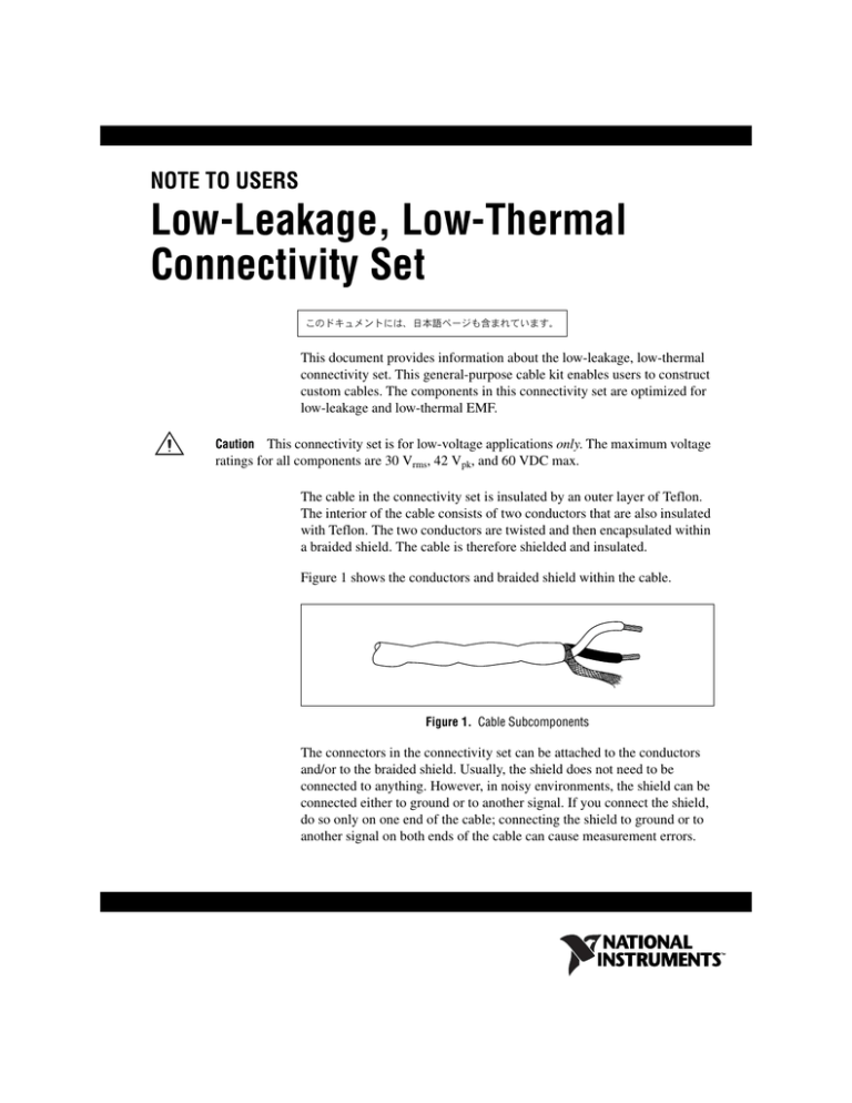
The cable in the connectivity set is insulated by an outer layer of Teflon.
The interior of the cable consists of two conductors that are also insulated
with Teflon. The two conductors are twisted and then encapsulated within
a braided shield. The cable is therefore shielded and insulated.
Figure 1 shows the conductors and braided shield within the cable.
Figure 1. Cable Subcomponents
The connectors in the connectivity set can be attached to the conductors
and/or to the braided shield. Usually, the shield does not need to be
connected to anything. However, in noisy environments, the shield can be
connected either to ground or to another signal. If you connect the shield,
do so only on one end of the cable; connecting the shield to ground or to
another signal on both ends of the cable can cause measurement errors.
Figure 2 provides an example of terminating the wires with connectors.
Although this figure shows spade lug terminals, you can attach other types
of terminals as needed.
Figure 2. Cable Wire Termination
Kit Contents
The following table contains connectivity set kit information
.
Component
Quantity
in Kit
Characteristics
Manufacturer*
Manufacturer
Part Number
Banana plug
terminals
• Gold plated, brass
6
Abbatron
(Formerly HH Smith)
425AA
Spade lug terminals
• Gold plated, uninsulated
• For use with 16–22 AWG† wire
10
Sunbelt Fasteners
761900-01
Ring lug terminals
• Gold plated, uninsulated
• For use with 26 AWG† wire
10
Sunbelt Fasteners
761901-01
Double banana plug
terminals
• Gold plated
• Black plastic casing
2
Pomona Electronics
4892
Teflon cable
•
•
•
•
3m
Belden
83319
Heat-shrink tubing
(small)
• Black
• 1/8 in. diameter
6 in.
Various electronics
supply stores
Varies
Heat-shrink tubing
(large)
• Black
• 1/4 in. diameter
6 in.
Various electronics
supply stores
Varies
Safety warning labels
(refer to Figure 5)
• Wraparound
• Adhesive
2
Sunbelt Fasteners
193548A-01
*
†
White casing
22 AWG† wire strand
Two conductors (white and black)
A braided shield
Most Components are also available through Sunbelt Fasteners.
American Wire Gauge.
Low-Leakage, Low-Thermal Connectivity Set Note to Users
2
ni.com
Connectivity Recommendations
Complete the following recommendations to minimize signal interference
when creating custom cabling:
•
NI recommends crimping and soldering components together. Before
soldering components, clean all surfaces with rubbing alcohol to
remove oil, grease, and any other contaminants. After soldering, clean
all surfaces again with rubbing alcohol to remove any solder paste or
other residues.
•
Although the gold-plated connectors reduce oxidation, avoid bringing
contaminants such as finger oil, grease, and flux into contact with the
connectors.
•
When using heat-shrink tubing, do not allow the heat-shrink tubing
around neighboring wires to touch, as Figure 3 shows.
No Contact
Figure 3. Avoiding Contact Between Heat-Shrink Tubing
Any contact between the heat-shrink tubing of adjacent wires creates a
leakage path between the connector terminals through the heat-shrink
tubing. However, Teflon is a higher-quality material than the
heat-shrink tubing, and it is acceptable for the Teflon-covered portions
of the wires to touch each other when bundled together.
•
When using the double banana plug terminal, consider wrapping the
cable through the strain-relief hole before tightening the screws down,
as Figure 4 shows.
Figure 4. Using the Strain-Relief Hole
•
© National Instruments Corporation
When taking high-precision measurements, ensure that the cable is
secure and free from vibration. Although Teflon has a very high
resistance, Teflon does experience triboelectric effects.
3
Low-Leakage, Low-Thermal Connectivity Set Note to Users
Safety Labels
Cautions This connectivity set is for low-voltage applications only. The maximum voltage
ratings for all components are 30 Vrms, 42 Vpk, and 60 VDC max.
This connectivity set contains safety warning labels that you must affix to the finished cable
to warn other users about the maximum voltage ratings.
Refer to Figure 5 and complete the following steps to affix the safety labels.
60 V
MAX
60 V
MAX
Figure 5. Affixing Safety Labels on Each End of the Cable
1.
Locate each end of the cable.
2.
On one end of the cable, position a label as close to the connector as
possible.
3.
Attach the label by peeling off the protective backing, folding the label
in half, and wrapping the label around the cable. The label adheres to
itself.
4.
Repeat steps 2 and 3 to affix a label to the other end of the cable.
National Instruments, NI, ni.com, and LabVIEW are trademarks of National Instruments Corporation. Refer to the Terms of Use section on
ni.com/legal for more information about National Instruments trademarks. Other product and company names mentioned herein are
trademarks or trade names of their respective companies. For patents covering National Instruments products, refer to the appropriate location:
Help»Patents in your software, the patents.txt file on your CD, or ni.com/patents.
© 2005–2007 National Instruments Corporation. All rights reserved.
371634B
Oct07


