Design and Analysis of a Novel Brushless Wound Rotor
advertisement
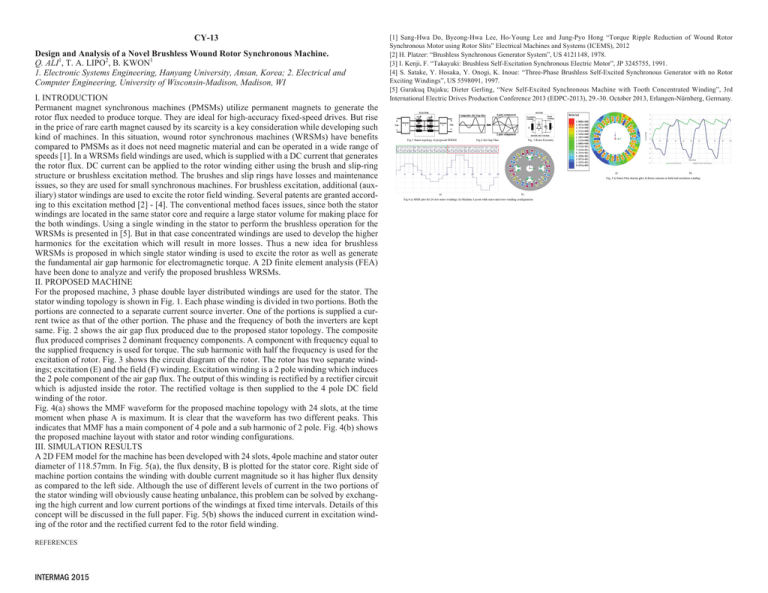
CY-13 Design and Analysis of a Novel Brushless Wound Rotor Synchronous Machine. Q. ALI1, T. A. LIPO2, B. KWON1 1. Electronic Systems Engineering, Hanyang University, Ansan, Korea; 2. Electrical and Computer Engineering, University of Wisconsin-Madison, Madison, WI I. INTRODUCTION Permanent magnet synchronous machines (PMSMs) utilize permanent magnets to generate the rotor flux needed to produce torque. They are ideal for high-accuracy fixed-speed drives. But rise in the price of rare earth magnet caused by its scarcity is a key consideration while developing such kind of machines. In this situation, wound rotor synchronous machines (WRSMs) have benefits compared to PMSMs as it does not need magnetic material and can be operated in a wide range of speeds [1]. In a WRSMs field windings are used, which is supplied with a DC current that generates the rotor flux. DC current can be applied to the rotor winding either using the brush and slip-ring structure or brushless excitation method. The brushes and slip rings have losses and maintenance issues, so they are used for small synchronous machines. For brushless excitation, additional (auxiliary) stator windings are used to excite the rotor field winding. Several patents are granted according to this excitation method [2] - [4]. The conventional method faces issues, since both the stator windings are located in the same stator core and require a large stator volume for making place for the both windings. Using a single winding in the stator to perform the brushless operation for the WRSMs is presented in [5]. But in that case concentrated windings are used to develop the higher harmonics for the excitation which will result in more losses. Thus a new idea for brushless WRSMs is proposed in which single stator winding is used to excite the rotor as well as generate the fundamental air gap harmonic for electromagnetic torque. A 2D finite element analysis (FEA) have been done to analyze and verify the proposed brushless WRSMs. II. PROPOSED MACHINE For the proposed machine, 3 phase double layer distributed windings are used for the stator. The stator winding topology is shown in Fig. 1. Each phase winding is divided in two portions. Both the portions are connected to a separate current source inverter. One of the portions is supplied a current twice as that of the other portion. The phase and the frequency of both the inverters are kept same. Fig. 2 shows the air gap flux produced due to the proposed stator topology. The composite flux produced comprises 2 dominant frequency components. A component with frequency equal to the supplied frequency is used for torque. The sub harmonic with half the frequency is used for the excitation of rotor. Fig. 3 shows the circuit diagram of the rotor. The rotor has two separate windings; excitation (E) and the field (F) winding. Excitation winding is a 2 pole winding which induces the 2 pole component of the air gap flux. The output of this winding is rectified by a rectifier circuit which is adjusted inside the rotor. The rectified voltage is then supplied to the 4 pole DC field winding of the rotor. Fig. 4(a) shows the MMF waveform for the proposed machine topology with 24 slots, at the time moment when phase A is maximum. It is clear that the waveform has two different peaks. This indicates that MMF has a main component of 4 pole and a sub harmonic of 2 pole. Fig. 4(b) shows the proposed machine layout with stator and rotor winding configurations. III. SIMULATION RESULTS A 2D FEM model for the machine has been developed with 24 slots, 4pole machine and stator outer diameter of 118.57mm. In Fig. 5(a), the flux density, B is plotted for the stator core. Right side of machine portion contains the winding with double current magnitude so it has higher flux density as compared to the left side. Although the use of different levels of current in the two portions of the stator winding will obviously cause heating unbalance, this problem can be solved by exchanging the high current and low current portions of the windings at fixed time intervals. Details of this concept will be discussed in the full paper. Fig. 5(b) shows the induced current in excitation winding of the rotor and the rectified current fed to the rotor field winding. REFERENCES INTERMAG 2015 [1] Sang-Hwa Do, Byeong-Hwa Lee, Ho-Young Lee and Jung-Pyo Hong “Torque Ripple Reduction of Wound Rotor Synchronous Motor using Rotor Slits” Electrical Machines and Systems (ICEMS), 2012 [2] H. Platzer: “Brushless Synchronous Generator System”, US 4121148, 1978. [3] I. Kenji, F. “Takayuki: Brushless Self-Excitation Synchronous Electric Motor”, JP 3245755, 1991. [4] S. Satake, Y. Hosaka, Y. Onogi, K. Inoue: “Three-Phase Brushless Self-Excited Synchronous Generator with no Rotor Exciting Windings”, US 5598091, 1997. [5] Gurakuq Dajaku; Dieter Gerling, “New Self-Excited Synchronous Machine with Tooth Concentrated Winding”, 3rd International Electric Drives Production Conference 2013 (EDPC-2013), 29.-30. October 2013, Erlangen-Nürnberg, Germany.
