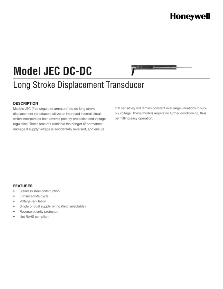
Model JEC DC-DC
Long Stroke Displacement Transducer
DESCRIPTION
Models JEC (free unguided armature) dc-dc long stroke
that sensitivity will remain constant over large variations in sup-
displacement transducers utilize an improved internal circuit
ply voltage. These models require no further conditioning, thus
which incorporates both reverse polarity protection and voltage
permitting easy operation.
regulation. These features eliminate the danger of permanent
damage if supply voltage is accidentally reversed, and ensure
FEATURES
•
Stainless steel construction
•
Enhanced life cycle
•
Voltage regulation
•
Single or dual supply wiring (field selectable)
•
Reverse polarity protected
•
Not RoHS compliant
Model JEC DC-DC
PERFORMANCE SPECIFICATIONS
RANGE CODES
Characteristic
Measure
Range Code
Available ranges
Stroke range
±12,7 mm to 203,2 mm [±0.5 in to 8.0
in]
HP
±12,7 mm [±0.5 in]
HQ
±25,4 mm [±1.0 in]
HR
±50,8 mm [±2.0 in]
HS
±76,2 mm [±3.0 in]
Non-linearity (max.)
±0.25 % full scale
Output load (min.)
2000 ohm with three-wire supply, 20000
ohm with floating supply
Output impedance
2 ohm
HT
±101,6 mm [±4.0 in]
Output sensitivity
±5 Vdc or 0 Vdc to 10 Vdc (field selectable)
HU
±152,4 mm [±6.0 in]
HV
±203,2 mm [±8.0 in]
Isolation
1000 V input to output
Polarity
Output is positive for outward stroke
ENVIRONMENTAL SPECIFICATIONS
OPTION CODES
Range Code
Many range/option combinations are available in
our quick-ship and fast-track manufacture programs. Please see http://sensing.honeywell.com/
TMsensor-ship for updated listings.
Characteristic
Measure
Temperature, operating
-50 °C to 70 °C [-58 °F to 158 °F]
Stroke ranges
±12,7 mm to 203,2 mm [±0.5 in to 8.0 in]
Temperature effect, zero
(max.)
0.006 % full scale/°F
Electrical
termination
Temperature effect, span
(max.)
0.017 % full scale/°F
Multiconductor shielded cable (1.83 m [6 ft])
TM405. Axial Bendix connector on body radial
(side)
TM406. Bendix connector on body
Electrical cable
orientation
TM49. Axial cable exit
Mounting
threads
TM511. 13/16-32 UNF
Improved
linearity
L10. ±0.1 % max. linearity (less than or equal to
±101.6 mm [±4 in])
ELECTRICAL SPECIFICATIONS
Characteristic
Measure
Element type
dc-dc displacement transducer
Power supply, single
24 Vdc to 40 Vdc @ 30 mA
Power supply, dual
±12 Vdc to ±20 Vdc @ 30 mA
Ripple power supply
30 mV peak to peak
Electrical termination
Multiconductor shielded cable (1.83 m
[6 ft])
Reverse polarity protection
Yes
MECHANICAL SPECIFICATIONS
Characteristic
Measure
Case material
Stainless steel
Probe material
Stainless steel
Armature type
Free unguided
Probe thread
M5 x 0.8
Weight
See table
Spring force (max.)
Not applicable
2 Honeywell • Sensing and Control
Long Stroke Displacement Transducer
MOUNTING DIMENSIONS
Range
code
Available stroke
range
L
X
Approx. body weight
Approx. armature
weight
HP
±12,7 mm [±0.5 in]
175,26 mm [6.9 in]
43,18 mm [1.7 in]
212,62 g [7.5 oz]
28,35 g [1.0 oz]
HQ
±25,4 mm [±1.0 in]
203,2 mm [8.0 in]
68,58 mm [2.7 in]
269,32 g [9.5 oz]
56,70 g [2.0 oz]
HR
±50,8 mm [±2.0 in]
317,5 mm [12.5 in]
81,28 mm [3.2 in]
368,54 g [13.0 oz]
70,87 g [2.5 oz]
HS
±76,2 mm [±3.0 in]
429,26 mm [16.9 in]
119,38 mm [4.7 in]
496,12 g [17.5 oz]
85,05 g [3.0 oz]
HT
±101,6 mm [±4.0 in]
474,98 mm [18.7 in]
132,08 mm [5.2 in]
623,69 g [22.0 oz]
99,22 g [3.5 oz]
HU
±152,4 mm [±6.0 in]
665,48 mm [26.2 in]
182,88 mm [7.2 in]
850,49 g [30.0 oz]
113,40 g [4.0 oz]
HV
±203,2 mm [±8.0 in]
855,98 mm [33.7 in]
259,08 mm [10.2 in]
1247,37 g [44.0 oz]
141,75 g [5.0 oz]
WIRING CODES
Wire
color
Dual supply
Single supply
(floating)*
Red
12 V to 20 V input
24 V to 40 V input
Blue
- 12 V to - 20 V
input
Supply negative
Black
O V, I/P, O/P common
For reference only
TYPICAL SYSTEM DIAGRAM
Outputs
Yellow
0 V to 10 V
Green
±5 Vdc
* Output common floats at voltage source/2
Honeywell • Sensing and Control 3
Model JEC DC-DC
NOTES
Long Stroke Displacement Transducer
1. GM-A should not be used with an amplified displacement transducer
unless using an external power supply to power the displacement
transducer.
Warranty. Honeywell warrants goods of its manufacture as
being free of defective materials and faulty workmanship.
Honeywell’s standard product warranty applies unless agreed
to otherwise by Honeywell in writing; please refer to your
order acknowledgement or consult your local sales office for
specific warranty details. If warranted goods are returned to
Honeywell during the period of coverage, Honeywell will repair
or replace, at its option, without charge those items it finds
defective. The foregoing is buyer’s sole remedy and is in lieu
of all warranties, expressed or implied, including those of
merchantability and fitness for a particular purpose. In no
event shall Honeywell be liable for consequential, special, or
indirect damages.
While we provide application assistance personally, through our
literature and the Honeywell web site, it is up to the customer to
determine the suitability of the product in the application.
Specifications may change without notice. The information we
supply is believed to be accurate and reliable as of this printing.
However, we assume no responsibility for its use.
For more information about Sensing and Control products, visit
www.honeywell.com/sensing or call +1-815-235-6847
Email inquiries to info.sc@honeywell.com
WARNING
PERSONAL INJURY
•DO NOT USE these products as safety or emergency
stop devices or in any other application where failure of
the product could result in personal injury.
Failure to comply with these instructions could result in
death or serious injury.
WARNING
MISUSE OF DOCUMENTATION
•The information presented in this catalogue is for
reference only. DO NOT USE this document as product
installation information.
•Complete installation, operation and maintenance
information is provided in the instructions supplied with
each product.
Failure to comply with these instructions could result in
death or serious injury.
Sensing and Control
Automation and Control Solutions
Honeywell
1985 Douglas Drive North
Golden Valley, MN 55422 USA
+1-815-235-6847
www.honeywell.com/sensing
008763-1-EN IL50 GLO May 2008
Copyright © 2008 Honeywell International Inc. All rights reserved.


