GE
Security
Overview
Standard Features
At the core of the GE fire solution is the EST3 platform, a globallyproven product deployed in some of the world’s most important
and high profile facilities. Now you can benefit from the confidence
of a world-leading platform that meets Australia’s and New Zealand’s
unique legislative standards.
•Meets international and Australian Fire Standards
including AS4428 Compliance
The EST3 is scalable to any size facility. You can be confident that the
system can handle your future growth. The EST3 fire system network
supports up to 64 panels, with each panel supporting up to 2,500
addressable points. It delivers a fast alarm response time across all
network sizes, and up to an overall length of 90 km. Even greater
distances can be achieved over fibre optic network using GE’s own
multi-mode or single mode fibre optic interface modules.
EST3 has a number of audio and visual warning options available to
complement its fire detection capability. For simple applications
24VDC Genesis signalling devices can provide basic cost effective
warning with synchronised T3 tones. For systems requiring PA and
single zone evacuation, GE offers a single zone OWS (Occupant
Warning System) that can be fitted within the 19” rackmount EST3
cabinets. For applications requiring a multi-zone warning and fire
phone system, EST3’s own integrated audio solution via plug in audio
and fire phone modules allows for up to eight channels of digital
audio anywhere on the EST3 network using just a single pair of wires.
For sites requiring an Emergency Warning and Intercommunication
System, GE’s EWIS is fully compliant to AS2220 Australian standards
and can even be fitted in the same 19” cabinet as an EST3 panel.
GE’s EST3 Fire Panel features high level integration with GE’s EWIS for
synchronised zone alarm and evacuation sequencing. The integration
enables both systems to communicate seamlessly eliminating costly
and cumbersome wiring of output modules to individual zone triggers
providing a more cost effective and robust integrated solution.
EST3 is built from the ground up to minimise labour and wiring costs
in new and retrofit installations, while making system maintenance
and even upgrades a breeze. In addition to supporting GE’s worldrenowned Signature series detectors, the EST3 platform will soon be
capable of backwards compatibility with GE‘s Ziton legacy detectors
and devices widely used in the Australian and New Zealand market.
(Expected late 2009)
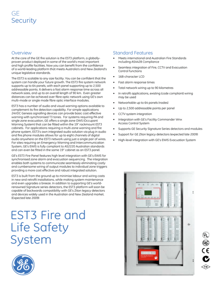
EST3 Fire and
Life Safety
System
•Seamless integration of Fire, CCTV and Evacuation
Control functions
• 168-character LCD
• Fast alarm response times
• Total network wiring up to 90 kilometres
•In retrofit applications, existing (code compliant) wiring
may be used
• Networkable up to 64 panels (nodes)
• Up to 2,500 addressable points per panel
• CCTV system integration
• Integration with GE’s Facility Commander Wnx
Access Control System
• Supports GE Security Signature Series detectors and modules
• Support for GE Ziton legacy detectors (expected late 2009)
• High-level integration with GE’s EWIS Evacuation System
Life Safety Redefined
Networking/Communications
The FireWorks PC-based graphic annunciation and event
management control package is available to coordinate system
events on a multi-sector display. This event-driven system places all
system events in immediate view and command of the operator.
Drivers are available for many major CCTV equipment manufacturers,
facilitating the smooth integration of CCTV with fire, and EWIS
(Evacuation) control functions. Cameras can automatically be directed
to preset locations and easily maneuvered by the operator, all from
the same screen.
The EST3 Life Safety Network uses a multi-priority peer-to-peer token
ring protocol. The protocol gives EST3 the exceptionally fast alarm
response time of less than three seconds across the network, virtually
independent of the total number of nodes. The EST3 token ring
network configuration also affords long distances between panels.
The distance between panels is 1,523 m for network control
signals (for 1.0 mm² cable). Supporting a maximum of 64 panels on
a network, the total network length can be in excess of 90 km.
Fibre optic media is also available.
Outstanding Features
Enhanced Reliability & Survivability
The EST3 is a modular life safety system uniquely designed to
meet the needs of any size facility, be it a single panel system or
a multi-panel network.
System components are arranged in layers, starting with the
backbox and finishing with inner and outer doors. Cabinets are
available with room for up to 20 modules and system batteries up
to 200 AH. A single 24-volt battery can act as the secondary power
supply for all four internal power supplies. Once the backbox is
installed, up to four power supplies can be installed in the chassis
assembly. The power supplies use a unique paralleling arrangement
that ensures the optimum use of each supply. Each supply has the
capacity to deliver up to 7 amps at 24 Vdc (28 amps total).
The function of each life safety network panel is determined by
the Local Rail Modules (LRMs) plugged into the panel’s chassis.
An extensive variety of modules are available, including central
processing units, input/output circuit modules, communication
modules, and loop drivers for Signature series detectors occupant
warning amplifiers and soon to be released (expected late 2009) loop
driver for GE legacy Ziton detectors. Please refer to the individual LRM
module catalogue sheets for specific details
of module functionality.
The top layer of the LRMs is referred to as the user interface layer. This
layer is made up of the Main Display Interface module and
a system of generic control/display modules. Any control/display
module can mount on any LRM. This maximizes flexibility of design
for custom systems. The inner and outer doors finish and secure
the enclosure.
A single panel can support up to 2,500 addressable points, provide
28 amps @ 24 Vdc, and still have room for future expansion.
If a single panel is not large enough or you need to distribute
functionality throughout the project, then you can network up to
64 panels together!
The EST3 uses distributed technology, designed to survive expected
and unexpected events. Intelligent Signature series detectors can
make alarm decisions on their own, and do not involve other system
components in this important decision-making process. Sensor-based
technology must communicate data to a remotely located common
panel where alarm decisions are made. Failure of this centralized
processor can cripple sensor-based systems. With EST3, a panel
CPU failure does not disable a panel’s ability to provide protection.
In the event of a CPU failure, the intelligent device controllers can
still receive alarms and distribute the alarm information to all other
modules in the panel. Modules in the panel are capable of responding
with a programmed standalone alarm response.
A single break or short on the network wiring causes the system
to isolate the fault, and network communication continues
uninterrupted – without any loss of function. Should multiple wiring
faults occur, the network re-configures into many sub-networks
and continues to respond to alarm events from every panel that can
transmit and receive network messages. Survivability is maximized
as responses originating and executed by a single panel are always
carried out because a copy of the system database is stored in the
panel’s memory.
Scheduled maintenance improves system availability, and EST3 is
designed to make system maintenance easy. System components are
designed to assist in routine and time-consuming service functions.
•EST3 service groups are defined by location, not by system wiring.
There is no need to disable an entire floor to test a single device.
•According to their UL listings, Signature Series detectors do not
require routine sensitivity testing*.
•Comprehensive internal and external monitoring quickly identifies
most problems to a component level, including ground faults that
can be identified down to the module.
•Parts are easy to replace. Modules plug in and use automatic
addressing and plug-in field wiring. No DIP switches are used.
•Firmware in system modules and Signature series devices is easily
upgraded as new advances in detection and control technology
are made available.
•Advanced system diagnostics are provided in the EST3 System
Definition Utility.
* Australian Standards require detectors to be routinely tested.
Feature Synopsis
User Friendly
A comprehensive survey of users resulted in system features
and controls that are easy to use.
•Agency Listing/Approval – Various components are approved by
ULI, ULC, C-tick, FM, CE, LPCB and Australian standards AS4428.
Please refer to individual component catalogue sheets for details.
The main display interface shows the operator the first and most
recent system events – without ever touching a single control!
All system events are sent to one of four message queues.
Alarm messages are never intermixed with fault or supervisory
signals, eliminating confusion. Need more information? The “Details”
switch provides additional information about the highlighted device.
The operator can easily review supervisory, fault, and monitor
messages by simply selecting the appropriate message queue.
After a few minutes of inactivity, the system automatically returns
to displaying the first and most recent events.
•System Components
•Industry standard 19” rack mount cabinets
•Power/Booster Supplies
•Central Processor Module
•Signature Controller
•Alphanumeric Display
Optional manual control switches and display modules can be
arranged on the system operator layer to suit the application.
These modules can be used to provide additional fan controls,
manual isolation of zones, or other required manual control functions.
•Control Display Modules
System Configuration
•Remote Annunciators
The powerful EST3 System Definition Utility (SDU) helps define flexible
system operations in a fraction of the time required by other systems.
Based on an object-oriented system of rules, virtually all EST3
operating features are software-controlled. This gives the designer
great flexibility in integrating fire, security, and access control
functions.
•FireWorks PC based graphic display and control with
CCTV interface
•Network Communication Cards
•Initiating Device Circuit Module (Conventional circuits)
Please refer to component catalogue sheets for additional details.
A report generator provides a complete library of system reports that
are invaluable for troubleshooting, including a printout of Signature
series device connections as the devices are actually wired.
Use of software-based components permits the SDU to add new
features to the system. Even the Signature Series devices are capable
of upgrading firmware as new detection algorithms become available.
From last
EST3
To next
EST3
Zone segregated
Speaker Circuit
Zone segregated
Speaker Circuit
1 Pair
EST3 Integrated Audio Speaker Circuit
P
CC
S
P
P
P
CC
1 Pair
PH
MS
S
P
S
CR
Relay
A/C (Shutdown)
CT
Input
(Flow switch)
P
Sounder/Strobe Circuits (24V DC)
Relay
Network Control
(Twisted Pair)
S
P
S
P
CR
CT
P
CT
1 Pair
Access
Control
EWIS
CC
MS
(ASE)
PIH
S MS
PH
CR
Single Input
(Flow Switch)
Dual Input
(Fan Monitor)
Relay
(Fan Control)
CT
Single/Dual Input Module
CR
Control Relay Module
Monitored Relay Module
CC
S
Nurse Call
P
H
FireWorks
CCTV
(Door Holder)
MS
MS
Photoelectric Smoke Detector
Heat Detector
PH
PIH
Combined Photoelectric and Heat Detector
Combined Photelectric, Ionisation and Heat Detector
Manual Call Point
Sounder/Speaker
Strobe
GE
Security
National Sales Enquiries
1300 361 479
Head Office
Victoria
Unit 3, 310 Ferntree Gully Road
Notting Hill 3168
T 61 3 9239 1200
F 61 3 9239 1299
Western Australia
Level 3, 6 Bennett Street
East Perth 6004
New South Wales
Level 1, 450 Victoria Road
Gladesville 2111
Queensland
Level 1, 143 Coronation Drive
Milton 4064
New Zealand
8 Tangihua Street
Auckland 1010
New Zealand
www.gesecurity.com.au
GE Security Pty Ltd
ABN 84 086 771 404
© 2009 General Electric Company
All Rights Reserved
AU-EST3-90727-B


