Rejuvenation Instructions
#521 – 200A Elbows – UPR
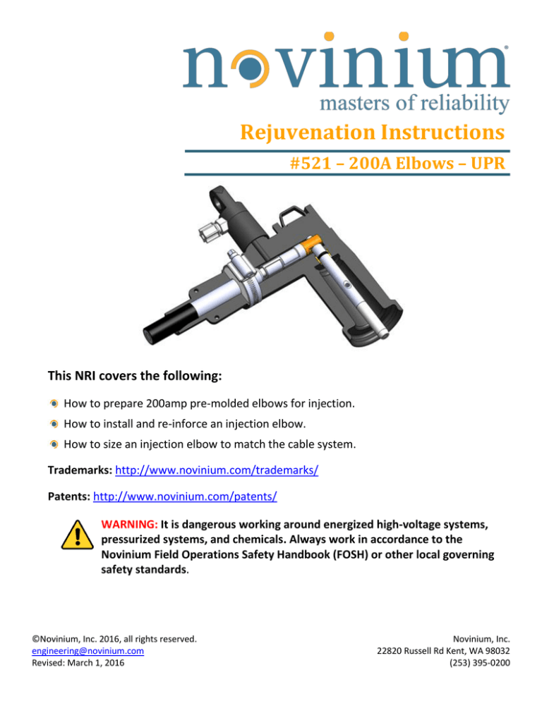
This NRI covers the following:
How to prepare 200amp pre-molded elbows for injection.
How to install and re-inforce an injection elbow.
How to size an injection elbow to match the cable system.
Trademarks: http://www.novinium.com/trademarks/
Patents: http://www.novinium.com/patents/
WARNING: It is dangerous working around energized high-voltage systems,
pressurized systems, and chemicals. Always work in accordance to the
Novinium Field Operations Safety Handbook (FOSH) or other local governing
safety standards.
©Novinium, Inc. 2016, all rights reserved.
engineering@novinium.com
Revised: March 1, 2016
Novinium, Inc.
22820 Russell Rd Kent, WA 98032
(253) 395-0200
Table of Contents
Introduction ............................................................................................................................................................................ 2
1.
Applications................................................................................................................................................................. 2
2.
Pressure rating. ........................................................................................................................................................... 2
3.
Limitations................................................................................................................................................................... 3
4.
Required equipment. .................................................................................................................................................. 3
Installing 200A Elbows ............................................................................................................................................................ 3
1.
Install the elbow.......................................................................................................................................................... 5
2.
Operations and maintenance. .................................................................................................................................... 5
Sizing Instructions ................................................................................................................................................................... 6
1.
Small-interface load-break elbows. ............................................................................................................................ 7
2.
Large-interface load-break elbows. ............................................................................................................................ 7
3.
Dead-break elbows. .................................................................................................................................................... 7
4.
Lugs. ............................................................................................................................................................................ 8
5.
Injection elbow accessories. ....................................................................................................................................... 8
©Novinium, Inc. 2016, all rights reserved.
Revised: March 1, 2016
NRI 521 – 200A Elbows – UPR
Page 1 of 8
Introduction
1. Applications.
200amp load-break and dead-break dead-front elbow terminations.
Three configurations (standard, extended, and repair length) injection elbows are available (Table 1).
Extended length and repair length injection elbows can make up 8 ¾” of cable length.
Configuration
Capacitive Test Point
Make-up Length
No
--
Yes
3¼”
Yes
8¾”
Standard Length
Extended Length
Repair Length
Table 1: Injection elbow configurations.
2. Pressure rating.
30psi.
©Novinium, Inc. 2016, all rights reserved.
Revised: March 1, 2016
NRI 521 – 200A Elbows – UPR
Page 2 of 8
3. Limitations.
Capacitive test points are available on the extended length and repair length injection elbows only.
The injection port adds 2½” to the back of an elbow and may not fit in smaller enclosures.
Injection caps are insulated and are not fully shielded with a semi-conductive layer.
Accessories for injection elbows such as injection caps, permanent caps, and probes are not
interchangeable between the two manufacturers (Cooper and Elastimold).
4. Required equipment.
Injection elbow.
Lug (for replacement).
Injection cap (for injection).
Probe kit (35kV Cooper elbows only).
Installing 200A Elbows
If you are installing an injection elbow on a cable that was not previously terminated with an elbow, follow
the instructions supplied with the elbow to trim the insulation and install the compression connector.
If you are retrofitting an injection elbow on a cable that was previously terminated, follow the steps below
and reference the manufacturer’s instructions where directed.
Carefully remove and discard the old probe and elbow. Clean the cable and remove grease or corrosion
inhibitor from around the conductor strands.
Measure the cable’s insulation diameter and use the tables at the end of this NRI to determine the
correct part number for the injection elbow.
Carefully inspect the existing craftwork including the insulation shield cutback, the insulation’s surface,
conductor strands, and the connector for damage. If the craftwork does not meet Novinium standards,
take corrective actions.
NOTE: All lugs that are not bi-metal (copper top) must be replaced.
©Novinium, Inc. 2016, all rights reserved.
Revised: March 1, 2016
NRI 521 – 200A Elbows – UPR
Page 3 of 8
Compare the existing cable prep
dimensions to the instruction sheet that is
included with the injection elbow and make
any necessary adjustments.
Figure 1: Instruction sheet example.
Adjust the insulation cutback as necessary
to expose ¼” to ½” of conductor strands
between the connector and insulation.
The conductor strands rotate around at a
15° angle. It is possible to create a suitable
flow path into the cable by opening the
conductor strands.
There are two methods to accomplish this goal:
1. Open the strands by rotating the
connector the opposite direction of the
strand lay by 15°.
Remember, 15° is the strand lay angle.
15°
¼” – ½“ gap
Figure 2: Check the gap and twist the connector to
open the conductors.
OR
2. Tighten the strands by rotating the
connector 15° in the strand lay’s
direction.
Then, rotate the connector back 15° to its
original position.
Examine for any strands that broke during
the rotation steps. Re-terminate if
necessary.
©Novinium, Inc. 2016, all rights reserved.
Revised: March 1, 2016
NRI 521 – 200A Elbows – UPR
Page 4 of 8
1. Install the elbow.
Lightly lubricate the surface of the cable’s insulation.
Do not apply lubrication to the inside of the elbow as the grease may accumulate around the
conductor strands and block flow.
Push the elbow onto the cable.
Lightly lubricate the o-ring on the probe and carefully install the probe.
Do not rotate the probe during insertion until the threads are engaged.
Use the torque wrench supplied in the kit or other approved tool to tighten.
Position the hose clamp on the thick portion
of the elbow and tighten until it just starts
to deform the surface of the rubber.
Do not remove the yellow warning tags from
the elbow or injection cap.
Figure 3: Position the hose clamp as shown.
2. Operations and maintenance.
The flow test and pressure test should only be performed using the injection cap that will be used for
injection in order to avoid contamination between cables.
Injection caps are shipped in sealed polyethylene bags and should be opened just prior to installation.
Re-using the injection cap and tubing is permitted.
o
The molded rubber should display no swelling, blisters or “belling”, and the black plastic stem
should be free of scratches.
o
Scratches on the stem can capture dirt and compromise its ability to function as a sealing surface
and insulating interface.
o
Long-term exposure to injection fluid can cause swelling that may compromise the injection cap.
o
Injection caps that no longer look like “new” must be discarded.
©Novinium, Inc. 2016, all rights reserved.
Revised: March 1, 2016
NRI 521 – 200A Elbows – UPR
Page 5 of 8
For storage between uses, the injection cap
and tubing should be fully drained of fluid,
and the outer surface of the tubing and the
inner surface of the injection cap should be
wiped clean.
o
The tubing should be neatly rolled and
then stored along with the injection cap
in a large re-sealable zip-lock bag.
o
Large re-sealable zip-lock bags are
available through Supply Chain by part
number 820122.
o
Prior to use, the injection cap should be
examined and cleaned.
Figure 4: Re-sealable plastic bag for storing injection
caps.
Permanent caps must be stored in a
polyethylene bag whenever they are not
installed on an injection elbow.
o
The re-sealable bags may also be
ordered separately by part number.
Figure 5: Re-sealable plastic bag for storing
permanent caps.
Sizing Instructions
Injection elbows are sized according to the insulation diameter of the cable. Elbows can be further
specified to match the system such as for load-break and dead-break configurations, single-phase and 3phase applications, 15, 25, 35kV systems, and with or without capacitive test points.
Figure 6: Size elbows according to the insulation diameter.
©Novinium, Inc. 2016, all rights reserved.
Revised: March 1, 2016
NRI 521 – 200A Elbows – UPR
Page 6 of 8
1. Small-interface load-break elbows.
Voltage
Rating
Elbow Type
Standard
15 kV
Extended w/ Test Port
Repair w/ Test Port
Standard
25 kV
Extended w/ Test Port
28 kV
Extended w/ Test Port
35 kV
Standard
Insulation Dia. DIM
"A"
Elastimold P/N
P/N
0.640" - 0.820"
168ALR-F
816119
0.767" - 0.950"
168ALR-G
816120
0.850" - 1.050"
168ALR-H
816121
0.980" - 1.180"
168ALR-J
816407
0.665" - 0.895"
168AELR-6689
816419
0.880" - 1.100"
168AELR-88110
818586
0.980" - 1.180"
168AELR-J
819183
0.640" - 0.820"
168ARLR-F
819141
0.767" - 0.950"
168ARLR-G
819142
0.767" - 0.950"
274ALR-G
816122
0.850" - 1.050"
274ALR-H
816123
0.880" - 1.100"
274AELR-88110
817299
0.980" - 1.180"
274AELR-J
819076
0.880" - 1.100"
274AELR-88110-CS854
819437
0.980" - 1.180"
274AELR-J-CS854
819815
0.980" - 1.180"
376ALR-J-5240
816544
Table 2: Small-interface load-break elbows.
2. Large-interface load-break elbows.
Voltage
Rating
Elbow Type
Insulation Dia.
DIM "A"
Cooper P/N
P/N
35 kV
Standard
0.995" -1.180"
LEIN235D00
8190651
Table 3: Large-interface load-break elbows.
3. Dead-break elbows.
Voltage
Rating
Elbow Type
Standard
15/25 kV
Extended w/ Test Port
Insulation Dia.
DIM "A"
Elastimold P/N
P/N
0.640" - 0.820"
156ALR-F-CS624
816418
0.850" - 1.050"
156ALR-H-CS624
816124
0.665" - 0.895"
156AELR-6689-CS624
820058
0.740" - 0.950"
156AELR-7495-CS624
820059
0.880" - 1.100"
156AELR-88110-CS624
818422
Table 4: Dead-break injection elbows.
©Novinium, Inc. 2016, all rights reserved.
Revised: March 1, 2016
NRI 521 – 200A Elbows – UPR
Page 7 of 8
4. Lugs.
Determine the cable size and use Table 5 to select the appropriate part number for an injection elbow lug.
Short Lug
Standard Lug
Extended Lug
Repair Lug
P/N
Conductor Size
Cooper Elbows
Standard
Extended
Repair Lugs
#4
Short Lugs
(Short Lugs)
-
816420
818746
-
#3
-
816421
-
-
#2
820025
816422
816525
819161
#1
820026
816423
816526
-
1/0
819146
816424
816527
819160
2/0
820027
816425
816528
-
3/0
-
816426
11556-11
-
4/0
-
816427
11556-21
-
Elastimold Elbows
Table 5: Injection elbow lugs.
5. Injection elbow accessories.
All available injection elbow caps, probes, and other accessories are provided in Table 6 below.
P/N
Description
Elastimold Elbows
Cooper Elbows
1-Phase
Caps
Probes
Injection
Permanent
10-Pack2
815629
815732
819068
819069
15 kV
816333
-
25 kV
25 kV
35 kV
816334
15/25 kV
820057
Load Break
Dead Break
3-Phase
819431
Spare O-Ring
816335
35 kV Kit
-
819067
1
819066
-
11377-1
11377-3
Table 6: Injection elbow accessories.
©Novinium, Inc. 2016, all rights reserved.
Revised: March 1, 2016
NRI 521 – 200A Elbows – UPR
Page 8 of 8


