CROUSE-HINDS
SERIES
MEDC signalling and alarms
BG manual call point range
Ex de, intrinsically safe (Ex ia),
weatherproof
Overview
Features
These manual alarm call points
have been designed for use in
hazardous locations and harsh
environmental conditions. The
glass reinforced polyester
enclosures are suitable for use
both onshore and offshore, where
light weight combined with a high
level of corrosion resistance is
required.
•
ATEX certified
•
SIL 2 certified
•
IECEx certified
•
A variety of colours available
•
UL certified for Haz locs
•
Up to 9 terminals available
•
UL certified for Ord locs
•
•
TR CU certified
Optional LED – indicates that the
unit has been operated
•
CQST certified
•
Earth continuity option for metal
glands
•
Brazilian (INMETRO) certified
•
1 or 2 changeover switches
•
CCOE certified
•
Captive cover screws
•
Chinese Compulsory Certification
for Fire systems (CCCF) certified
•
Key operated test facility – simple
but secure
•
IP66 and IP67
•
Breakglass hammer available
•
Corrosion free GRP construction
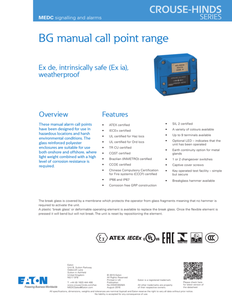
The break glass is covered by a membrane which protects the operator from glass fragments meaning that no hammer is
required to activate the unit.
A plastic ‘break glass’ or deformable operating element is available to replace the break glass. Once the flexible element is
pressed it will bend but will not break. The unit is reset by repositioning the element.
Eaton
Unit B, Sutton Parkway
Oddicroft Lane
Sutton in Ashfield
United Kingdom
NG17 5FB
T: +44 (0) 1623 444 400
www.crouse-hinds.com/hac
MEDCSales@Eaton.com
© 2015 Eaton
All Rights Reserved
Printed in UK
Publication
No.DSMC0029/A
August 2016
Eaton is a registered trademark.
All other trademarks are property
of their respective owners.
Please check here
for latest version of
the datasheet
All specifications, dimensions, weights and tolerances are nominal (typical) and Eaton reserve the right to vary all data without prior notice.
No liability is accepted for any consequence of use.
Certifications
General arrangement drawing (all dimensions in mm)
ATEX Ex de
Cert. no. BAS02ATEX2105X. ATEX Approved Ex II 2G
Certified to: EN60079-0, EN60079-1, EN60079-7
Ex de IIC T6 Gb switch only
Ex de mb IIC T6 Gb with LED
Ex de mb IIC T4 Gb with resistors & diodes
ATEX Ex ia
Cert no. Baseefa 03ATEX0084X. ATEX approved Ex II 1GD
Certified to: EN60079-0, EN60079-11
Ex ia IIC T4 Ga, Ex ia IIIC T135°C Da
IECEx Ex ia
Cert. no. IECEx BAS 12.0093X
Certified to: IEC 60079-0, IEC 60079-11
Ex ia IIC T4 Ga, Ex ia IIIC T135°C Da
UL
Listing no. E186629
UL listed to Class 1, Div 2. Groups A – D
UL listed for ordinary locations. Listing no. S8117
TR CU Ex ed
2Ex ed IIC T6, DIP A21 T85°C IP66/IP67 (switch only)
2Ex e md IIC T4, DIP A21 T135°C IP66/IP67 (other versions)
Russian Fire approved
TR CU Ex ia
Ex ia IICT4. Russian Fire approved
INMETRO Ex de
Ex de mb IIC T4 Gb, Ex de IIC T6 Gb
CQST Ex de
Ex de IICT6 (switch only), Ex de m IICT4 (other versions)
CQST Ex ia
Ex ia IIC T4
CCCF
Chinese Compulsory Certification for Fire systems (CCCF). Ex de only
SIL
SIL 2 certified to IEC 61508. Cert no. Sira 11013
Type approvals
American Bureau of Shipping type approval (ABS)
Specifications
Material
Anti-static UV resistant glass reinforced polyester
Finish
Red painted finish as standard or to customer specification
Voltage
Up to 254V a.c. Up to 28V d.c
Weight
1.2 kg. (varies with models and entries)
Ingress protection
IP66 & IP67
Entries
Up to 4 entries, M16 or M20 top and bottom (1/2” NPT available on UL
version)
Terminals
7 x 2.5mm2 - non UL standard
9 x 2.5mm2 - optional (up to 60V only)
6 x 12AWG - BGUL only
Resistors
Various configurations available on versions up to 24V and all ‘IS’ versions
(minimum resistor value 100ΩBGE, 470ΩBGI)
Earth continuity
Internal and external earth continuity is provided with an optional
earth plate
LED indication
A high intensity red LED can be fitted as an optional extra to indicate
operation on versions up to 24V and all ‘IS’ versions
As standard the LED is not provided with over current protection. The forward
current (If) should be limited to 20mA
Labelling
BG glass label – reads either (1) Fire Break glass – press here
(2) Break glass – press here
(3) Worded to customer requirements
(7) Dot and arrows - no text
Duty label – worded to customer requirements. Riveted on
Tag label – worded to customer requirements. Screwed on
Switch ratings (1 or 2
changeover switches
fitted)
dc 0-30v 5A (resistive) or 3A (inductive)
30-50v 1A (resistive or inductive)
ac 0-254V 5A (resistive or Inductive)
Ordering requirements
BG standard wiring configuration
Temperature:
Model
BGW
BGUL
BGE
-40ºC to
-25ºC to
-40ºC to
+70ºC
+55ºC†
+70ºC*
*-35ºC to +70ºC with LED
† -25°C to +50°C with resistors or LED fitted
BGI
-40ºC to
+70ºC
The following code is designed to help in selection of the correct unit. Build up the reference number by inserting the code for each component into the appropriate box
Note: For CCCF units use the following code: BGEQF4B6B74DSA_9R. Add a code in the blank space only if resistors are required. The possible codes are C, D or S as
per the options box below
Model
Certification
Entries
Labels
Voltage
Switches
Options
Terminals
Finish
BG
Certification
ATEX/CENELEC - Ex de
ATEX/CENELEC - Ex ia
IECEx - Ex ia
UL - Listed
UL (Ordinary Locations)
TR CU - Ex ia
TR CU Ex ed
CQST - Ex de
CQST/CCCF - Ex de
CQST - Ex ia
INMETRO - Ex de
Uncertified
†Not suitable for use in
China on fire alarm systems
Code
EB
IB
IJ
UL
UW
IG
EG
EG†
EQF
IQ†
EM
WN
Entries
M16
M20
½” NPT
Code
Label
1
Glass label (1) reqd
2
Glass label (2) reqd
3*
Glass label (3) reqd
4*
Duty label reqd
5*
Tag label reqd
7
Glass label (7) reqd
*Specify wording on 3, 4 or
5 as required
Voltage
a.c
d.c
Code *Prefix entry size (see diagram
above) with entry position
A*
code e.g. 4B6B
B*
UL versions only available
C*
with 1/2” NPT entries
Code
Switches
S
Single changeover
Double changeover D
Code
Terminals
6 x 12AWG (UL standard) 6*
7
7 x 2.5mm (standard)
9
9 x 2.5mm (optional)
*BGUL only available with six terminals
Code
A
D
Code
Finish
R
Red (standard)
N
Natural black
B
Blue
Y
Yellow
G
Grey
X
Yellow/black stripes
S*
Special
Code
Option
N
None
A
LED
B
Lift flap
C*
Resistor series
D*
Resistor EOL
*Please specify
E‡
Diode
F‡
Earth continuity
S*† *Specify values
Resistor series and EOL
Plastic element replaces
†Choose for BGE only P
break glass
on the BGI/W, choose C & D
H
Break glass hammer
‡Not available for UL versions
DSMC0029/A
08/16


