Bulletin No. 65013-004-11D
June 2000
Raleigh, NC, USA
Instruction Bulletin
Replaces 65013-004-11B dated 6/94
Standard and Push-to-Test Pilot Lights
and Illuminated Push Buttons
Class 9001, Types TP/TPM and TPK, Series H
Retain for future use.
INTRODUCTION AND
INSTALLATION PROCEDURE
This bulletin describes how to install Class 9001, Types TP/TPM and TPK
standard and push-to-test pilot lights and illuminated push buttons.
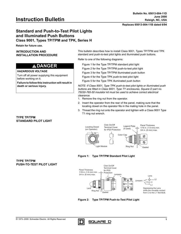
Refer to one of the following diagrams:
DANGER
HAZARDOUS VOLTAGE
Turn off all power supplying this equipment
before working on it.
Failure to follow this instruction will result in
death or serious injury.
Figure 1 for the Type TP/TPM standard pilot light
Figure 2 for the Type TP/TPM push-to-test pilot light
Figure 3 for the Type TP/TPM illuminated push button
Figure 4 for the Type TPK push-to-test pilot light
Figure 5 for the Type TPK illuminated push button
NOTE: If Class 9001, Type TPK push-to-test pilot lights or illuminated push
buttons are fitted in Class 9001, Type TY enclosures, Square D part no.
75030-765-50 insulator kit must be used to achieve correct electrical
clearance.
1. Remove the ring nut from the operator.
2. Insert the operator from the rear of the panel, making sure that the
locating dowel on the operator fits in the mating hole in the panel.
3. Thread the ring nut onto the operator and tighten with a Class 9001 Type
T1 ring nut wrench.
TYPE TP/TPM
STANDARD PILOT LIGHT
Locating Dowel
(on Operator)
Click On/Off
Terminal Cover
for IP20 Protection
Legend Plate
(if used)
Panel Thickness
1/16 in. (1.6 mm) min.
3/4 in. (6 mm) max.
Color Cap
Light Module
Figure 1:
Ring Nut
Gasket
Type TP/TPM Standard Pilot Light
TYPE TP/TPM
PUSH-TO-TEST PILOT LIGHT
Panel Thickness
1/16 in. (1.6 mm) min.
3/4 in. (6 mm) max.
Click On/Off
Terminal Cover
for IP20
Protection
Jumpers
Lens
Jumpers
Lens
Ring Nut
Figure 2:
© 1973–2000 Schneider Electric All Rights Reserved
Gasket
L2
C
L1
Depressing the Lens
shifts the movable contact
from C to the L1 Test Bulb.
Type TP/TPM Push-to-Test Pilot Light
1
Standard and Push-to-Test Pilot Lights and Illuminated Push Buttons
Class 9001, Type TP/TPM and TPK, Series H
Bulletin No. 65013-004-11D
June 2000
TYPE TP/TPM
ILLUMINATED PUSH BUTTON
Panel Thickness
1/16 in. (1.6 mm) min.
3/4 in. (6 mm) max.
Panel Drilling
(All Units)
Click On/Off Terminal
Cover for IP20 Protection
Legend Plate (if used)
Ring Nut with Guard
DIA = 0.136 in. (3.5 mm)
Min. 1/16 in. (1.6 mm) deep
3/4 in.
(19 mm)
Color Cap
Ring Nut
(Operator
without Guard)
Figure 3:
DIA = 1-7/32 in. (31 mm)
Gasket
Type TP/TPM Illuminated Push Button
TYPE TPK
PUSH-TO-TEST PILOT LIGHT
Panel Thickness
1/16 in. (1.6 mm) min.
3/4 in. (6 mm) max.
Click On/Off
Terminal Cover
for IP20
Protection
Jumpers
Lens
Jumpers
L2
C
L1
Depressing the Lens
shifts the movable contact
from C to the L1 Test Bulb.
Lens
Ring Nut
Figure 4:
Gasket
Type TPK Push-to-Test Pilot Light
TYPE TPK
ILLUMINATED PUSH BUTTON
Panel Thickness
1/16 in. (1.6 mm) min.
3/4 in. (6 mm) max.
Click On/Off Terminal
Cover for IP20 Protection
DIA = 0.136 in. (3.5 mm)
Min. 1/16 in. (1.6 mm) deep
Ring Nut withGuard
3/4 in.
(19 mm)
Color Cap
Ring Nut
(Operator
without Guard)
Figure 5:
Square D Company
8001 Hwy 64 East
Knightdale, NC 27545 USA
1-888-SquareD (1-888-778-2733)
www.squared.com
2
Panel Drilling
(All Units)
DIA = 1-7/32 in. (31 mm)
Gasket
Type TPK Illuminated Push Button
Electrical equipment should be serviced only by qualified personnel. No responsibility is assumed
by Schneider Electric for any consequences arising out of the use of this material.
© 1973–2000 Schneider Electric All Rights Reserved
