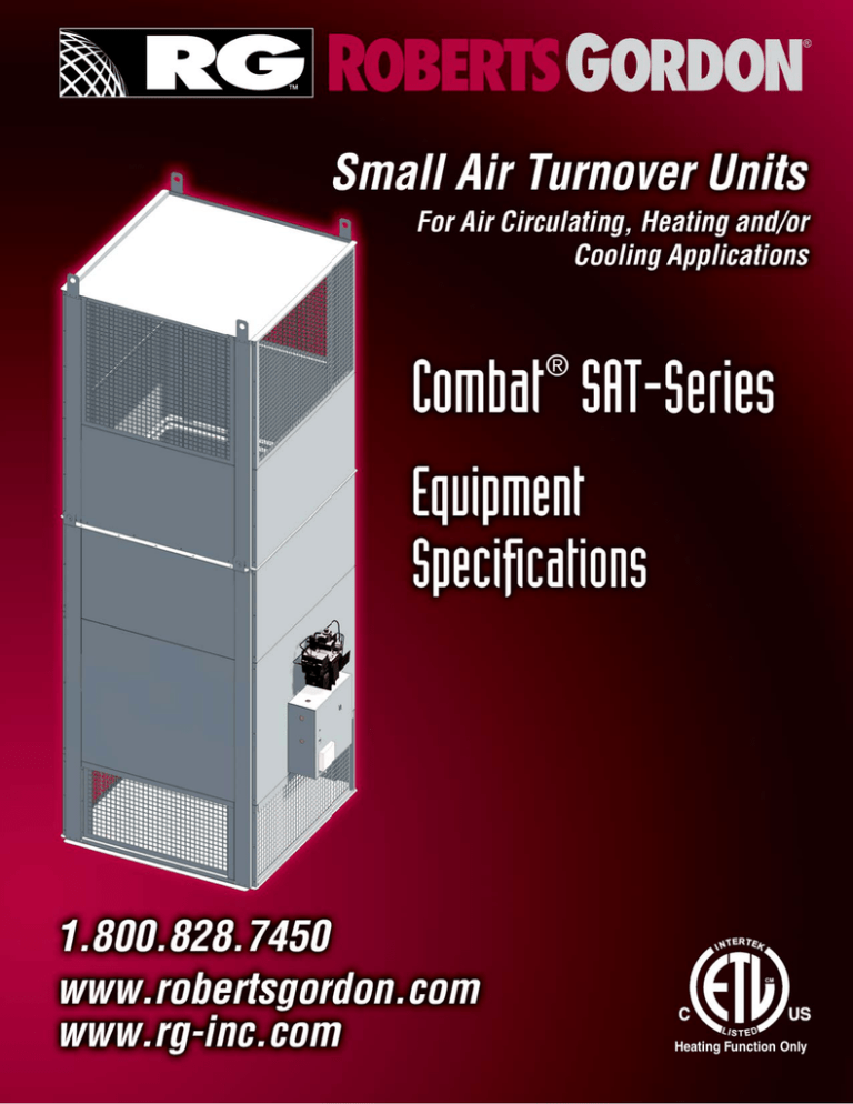
Heating Function Only
SMALL AIR TURNOVER UNIT GUIDE SPECIFICATIONS
PART 1: GENERAL
(Please note: Brackets indicate required choices to be made in preparation of the
final specification.)
Provide air turnover unit with fan [heating][cooling] sections,
designed and manufactured for indoor installation.
1.1 SECTION INCLUDES
A. Air turnover unit
B. Controls
1.2 REFERENCES
A. American National Standards Institute (ANSI) / Canadian
Standards Association (CSA): Establish requirements applicable
to construction, certification and installation of units.
1. Standard ANSI Z83.8 / CSA 2.6 “Gas Unit Heater and GasFired Duct Furnaces” (latest edition)
B. American Society for Testing Materials (ASTM): Establishes
standards for materials, products, systems and services.
1. Standard A653/653M: Standard Specification for Steel
Sheet, Zinc-Coated (Galvanized) or Zinc-Iron Alloy
Coated (Galvannealed) by the Hot Dip Process
C. ETL Testing Laboratories, Inc. (ETL): Nationally recognized
testing laboratory certifies code conformance.
1. Requirements applicable to product labeling and listing in
the Directory of ETL Listed Products.
D. Fire Protection Association (NFPA): Establishes fire prevention
standards.
1. Article 54: National Fuel Gas Code (latest edition)
2. Article 70: National Electric Code (latest edition)
1.3 SUBMITTALS FOR REVIEW
A. Product Data: Provide data with dimensions, service
connections, accessories, controls, electrical nameplate data and
wiring diagrams.
B. Submittal Drawings: Indicate dimensions, service connections,
controls, electrical nameplate data and wiring diagrams.
1.6 QUALITY ASSURANCE
A. Manufacturer Qualifications: Company specializing in
manufacturing the products specified in this section (air turnover
unit) with a minimum of ten years documented experience.
Equipment shall be the standard product of the manufacturer and
shall have complete cataloged data.
B. Installer Qualifications: All installation and service of air
turnover units must be performed by a contractor qualified
in the installation and service of said products with proof of a
minimum of three years documented experience.
C. Factory Testing: Each air turnover unit shall be factory-tested.
Testing shall consist of verification of correct operation of
burner, manifold, control assembly and electrical components.
1.7 REGULATORY REQUIREMENTS
A. Conform to the National Fuel Gas Code (NFPA 54/ANSI
Z223.1).
1.8 WARRANTY
A. The product shall have a manufacturer's limited warranty of at
least 24 months, subject to the manufacturer's standard warranty
limitations.
PART 2: PRODUCTS
2.1 MANUFACTURERS
A. COMBAT® SAT-Series air turnover unit that shall incorporate
one of the following styles:
•
Air-only
•
Heat-only
•
Cool-only
•
Heat-cool combination
2.2 MANUFACTURED UNITS
A. Unit: Constant volume indoor air turnover unit
1.4 SUBMITTALS FOR INFORMATION
2.3 FABRICATION
A. Manufacturer’s Instructions: Indicate rigging, assembly and
installation instructions.
1.5 SUBMITTALS AT PROJECT CLOSEOUT
A. Casing and Components: Air turnover unit to be constructed of
minimum 20 ga galvanized steel panels and reinforced with an
integral frame. The entire cabinet shall be lined with 1" (2.5 cm)
1.5lb. density insulation.
A. Operation and Maintenance Data: Include manufacturer’s
Installation, Operation and Service Manual.
B. Lifting Points: The lifting lugs shall be provided on the top
corners of each section of the air turnover unit.
B. Warranty: Submit manufacturer’s warranty and ensure forms
have been filled out in owner’s name and registered with the
manufacturer.
C. Finish: White air dry enamel is standard finish.
C. Training: Provide owner with verbal operating instructions, as
well as original manufacturer’s installation, operation and service
manuals.
D. Observation Port: A permanent observation port shall be
provided to allow observation of the main flame.
E. Filters: Filter racks shall be mounted on the exterior of each side
of the inlet plenum. 1" (2.5 cm) thick polyester filters shall be
provided.
2.4 BURNER/MANIFOLD
2.8 CONTROL SYSTEM
A. Burner: Furnish and install one 400 MBH (117.2 kW) input on/
off gas burner. The burner shall incorporate a stainless steel
flame retention type combustion head. Combustion head shall
be symmetrically round. Primary-secondary air control shall be a
design function of the combustion head. The burner shall include
automatic ignition controls, flame failure system and low gas
pressure switch.
A. Control Enclosure: A factory-wired control cabinet shall be
mounted to the unit. Cabinet shall house burner and motor
overloads and fuses, control switches, relays, transformer, circuit
breakers and terminal strips. Fan/blower motor will be wired to
the motor starter.
B. Manifold: The manifold shall be composed of a manual shut-off
valve, pressure regulator, auxiliary gas valve and main gas valve
on main line. The manifold shall include a 1/8" NPT pressure
tapping with 1/8" pipe plug upstream and downstream of valve
and regulator. Maximum inlet gas pressure is 14" w.c.
2.5 HEAT EXCHANGER
A. Heat Exchanger: Heat exchanger shall incorporate primary
surface drum and secondary surface tubes in a three-pass design
with a minimum thermal efficiency of 85%. Baffles are to be
utilized to assure proper air distribution on the heat exchanger.
The primary surface is to be no less than 16 gauge 321 stainless
steel. The secondary tubes are to be no less than 12 gauge corten
steel and no greater than 2.5" (6.4 cm) in diameter. The front
and rear headers are to be no less than 12 gauge corten steel.
2.6 COOLING COIL
A. Cooling Coil: Coil shall be 20 tons (70.3 kW), of an A-frame
design with two circuits and shall be mounted in the discharge
head of the unit.
2.7 FANS AND MOTORS
A. Fan: The fan shall be a 42" (106.7 cm) diameter heavy-duty
propeller-type constructed of 10ga blades. Blower shaft shall be
of a solid design.
B. Drive: All V-belt drives shall be standard capacity, with two
reinforced rubber belts. The sheaves shall be of a cast iron type.
Standard drive sheaves are adjustable with a plus or minus 10%
adjustability. The service factor used for V-belt drives shall be
not less than 1.3.
C. Fan Bearings: Fan shall be supported by two pillow-block
bearings. Bearings shall be of a greasable, self-aligning, ball
bearing type.
D. Motor: Motor shall be [230/1/60 standard efficiency TEFC]
[208/3/60 premium efficiency TEFC] [230/3/60 premium
efficiency TEFC] [460/3/60 premium efficiency TEFC]
[575/3/60 premium efficiency TEFC]. Motor horsepower shall
be as indicated on the schedule. All motors shall be controlled
and protected by an automatic starter with thermal overload
protection. Starter shall be interlocked to prevent burner
operation when overload relays are tripped.
E. Sound Power: The fan sound power shall not exceed 77 dBA at a
distance of 5 feet (1.5 m) from the air turnover unit.
B. Disconnect Switch: A fused rotary disconnect switch shall be
factory-mounted on the outside of the control enclosure door.
C. Temperature Controller: A temperature controller shall be
factory-provided, driven by a factory-provided thermostat
mounted on the outside of the control enclosure door.
Thermostat shall consist of at least two stages of control for both
the heating and cooling cycles. The thermostat shall also have
programming capability, including 4 stages per day and 7 days of
independent programming.
D. Unit-Mounted On/Off Switch: An on/off switch shall be factoryprovided for manual operation of the small air turnover unit.
It includes a double-pole, single-throw (DPST) rocker switch
mounted on the outside of the control enclosure door.
E. Safety Controls
1. Flue Blockage Airflow Switch: A flue blockage airflow
switch shall turn the burner off and illuminate a warning
light mounted on the outside of the control enclosure
door when the backpressure in the heat exchanger exceeds
its setpoint. The airflow switch shall be factory set at 0.47”
w.c. (1.2 mbar).
2. Compressor Interlock Airflow Switch: A compressor
interlock airflow switch shall not allow the compressor in
the paired condensing unit to turn on until airflow is
proven. The airflow switch shall be factory set at 0.47” w.c.
(1.2 mbar).
3. High Temperature Limit Switch: A high temperature limit
switch shall turn the burner off when air is discharged
above its setpoint. The high temperature limit switch shall
be factory set at 122° F (50° C).
4. Low Gas Pressure Switch: The low gas pressure switch
shall turn the burner off when the gas pressure is below its
setpoint. The minimum gas pressure shall be set at 5.5”
w.c. (13.7 mbar).
2.9 PERFORMANCE
A. See Schedule on plans.
PART 3: EXECUTION
3.1 INSTALLATION
A. The air turnover unit shall be started per the instructions
in the Installation, Operation, and Service Manual by the
installing contractor. A factory provided field start up
form shall be filled out by the contractor and mailed to the
manufacturer. The start-up shall include, but not be limited
to:
•
Verification of proper supply power and fuel.
•
Verification that electrical terminals are secure.
•
Proper air flow balance.
•
Verification of combustion efficiency and proper burner
adjustments
•
Testing of all safety and operating controls.
•
Setting of high fire.
B. One copy of the Installation, Operation, and Service
Manual shall be enclosed in the control panel. The manual
shall consist of recommended installation procedures
and guidelines, inspection, initial start-up, operating,
maintenance and troubleshooting sections.
3.2 SCHEDULES
A. See plans.
Installation Code and Annual Inspections:
All installation and service of ROBERTS GORDON equipment must be performed by a contractor qualified in the installation and
service of equipment sold and supplied by Roberts-Gordon LLC and conform to all requirements set forth in the ROBERTS GORDON
manuals and all applicable governmental authorities pertaining to the installation, service, operation and labeling of the equipment. To
help facilitate optimum performance and safety, Roberts-Gordon LLC recommends that a qualified contractor conduct, at a minimum,
annual inspections of your ROBERTS GORDON equipment and perform service where necessary, using only replacement parts sold
and supplied by Roberts-Gordon LLC.
Further Information: Applications, engineering and detailed guidance on systems design, installation and equipment performance is
available through ROBERTS GORDON representatives. Please contact us for any further information you may require, including the
Installation, Operation and Service Manual.
These products are not for residential use.
This document is intended to assist licensed professionals in the exercise of their professional judgment.
®
®
®
®
Roberts-Gordon LLC
1250 William Street
P.O. Box 44
Buffalo, NY 14240-0044 USA
Telephone: +1.716.852.4400
Fax: +1.716.852.0854
Toll Free: 800.828.7450
www.robertsgordon.com
www.rg-inc.com
© 2012 Roberts-Gordon LLC All rights reserved. No part of this work covered by the copyrights herein may be reproduced or copied in any form or
by any means – graphic, electronic, or mechanical, including photocopying, recording, taping, or information storage
and retrieval systems – without written permission of Roberts-Gordon LLC.
Printed in U.S.A.
SATESNA
0912 Orig.


