Model : RM - 5 DPDT Form
advertisement
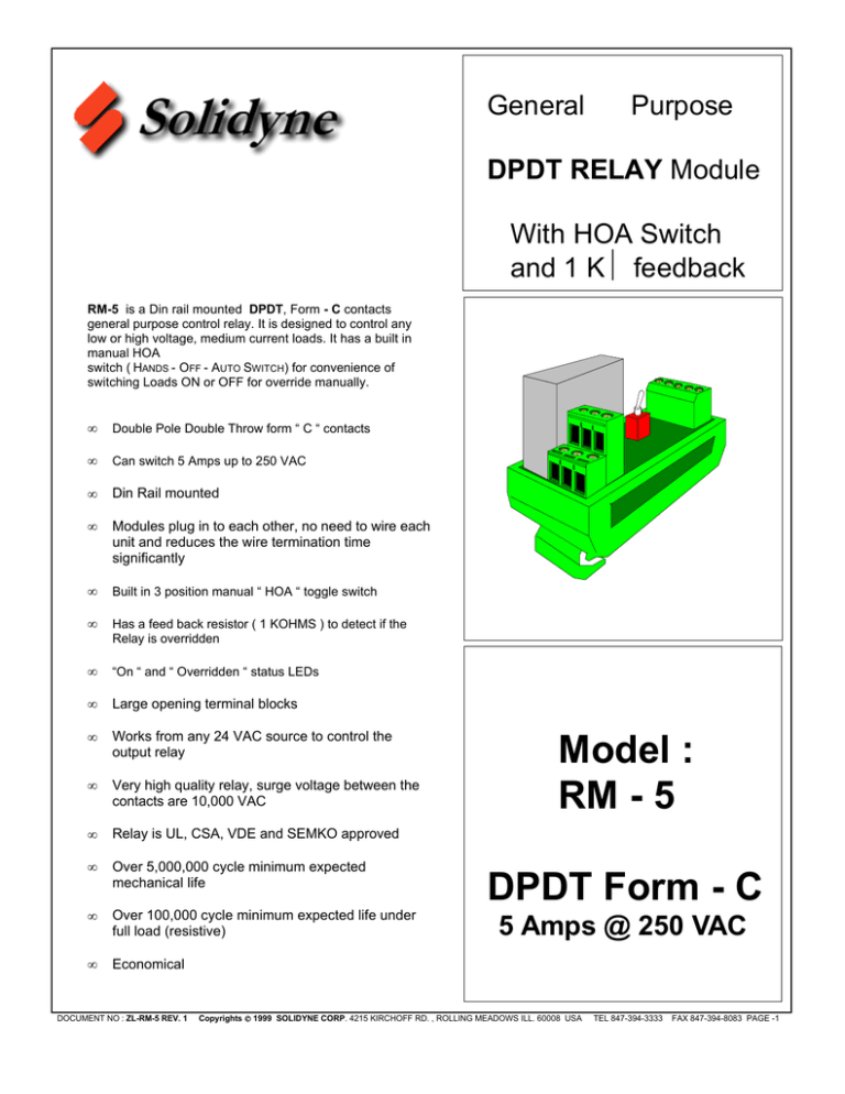
General Purpose DPDT RELAY Module With HOA Switch and 1 KΩ feedback RM-5 is a Din rail mounted DPDT, Form - C contacts general purpose control relay. It is designed to control any low or high voltage, medium current loads. It has a built in manual HOA switch ( HANDS - OFF - AUTO SWITCH) for convenience of switching Loads ON or OFF for override manually. • Double Pole Double Throw form “ C “ contacts • Can switch 5 Amps up to 250 VAC • Din Rail mounted • Modules plug in to each other, no need to wire each unit and reduces the wire termination time significantly • Built in 3 position manual “ HOA “ toggle switch • Has a feed back resistor ( 1 KOHMS ) to detect if the Relay is overridden • “On “ and “ Overridden “ status LEDs • Large opening terminal blocks • Works from any 24 VAC source to control the output relay • Very high quality relay, surge voltage between the contacts are 10,000 VAC • Relay is UL, CSA, VDE and SEMKO approved • Over 5,000,000 cycle minimum expected mechanical life • Over 100,000 cycle minimum expected life under full load (resistive) • Economical DOCUMENT NO : ZL-RM-5 REV. 1 Model : RM - 5 DPDT Form - C 5 Amps @ 250 VAC Copyrights 1999 SOLIDYNE CORP. 4215 KIRCHOFF RD. , ROLLING MEADOWS ILL. 60008 USA TEL 847-394-3333 FAX 847-394-8083 PAGE -1 OPERATION : RM - 5 is designed to operate from a 24 VAC control voltage signal. It is primarily designed for control panels where there are number of such relays are installed. The module has many features built in that are useful, convenient and reduce cost of wiring very significantly. These features are as follows : Additionally, the feedback resistors are connected in series via these connectors. Hence, only the first and last module needs to be wired (2 terminations) to the Sensor Common and Sensor Input of the Controller. 4. It has 2 status LEDs. RED LED indicates if the relay is energized. The second YELLOW LED is for Override indicator, which turns along with the RED LED if it is overridden ON. 1. RM - 5 has built in 3 position HOA override switch. The relay output can be overridden to be OFF ( deenergized), ON (energized) or operate Automatically by the controlling signal. RM - 5 is designed to be mounted on a DIN rail. This allows multiple modules to be snapped on to the DIN rail without any additional labor. This saves time and allows future flexibility. 2. It has a 2 wire Feedback signal This signal is a resistor which has a value of “ 0 “ Ohm (short) in Auto mode and becomes 1.00 Kilo Ohms if it is overridden to be ON or OFF. This feature can be used with any Controller as a feedback signal where if the resistance is any value other than 0 ohms, it is overridden. 3. The modules have a unique design where one module plugs into a module next to it. Each module has a two (3 pins) connectors on the side. One set is mail and the other one is female and they mate. If one module is wired for 24 VAC HOT and Return, then all the other modules will be powered for 24 VAC via these 3 pin connectors, if they are plugged into each other. RM - 5 has a very reliable in relay. It is specifically design for control applications where the voltage break down between the contacts and contacts to the relay coil is exceptionally high. It is in excess of 10,000 volts. If the relay contacts are switching electrically noisy and very inductive loads they will generate a lot of voltage transients and spikes they are turned on and off. Due to very high voltage isolation between the contacts and the relay coil, the Controller will further be protected from these high voltage transients. The module has very long mechanical and electrical life for control applications. INPUT WIRING TERMINAL BLOCK MATING 3 TERMINAL MALE CONNECTOR YELLOW OVERRIDE STATUS LED. IT WILL TURN ON IF THE TOGGLE SWITCH IS ON RED STATUS LED. IT WILL TURN ON IF THE RELAY IS ENERGIZED FEED BACK 24 VAC CTRL 24 VAC COM INPUT HOT 3 TERMINAL FEMALE CONNECTOR OVERRIDDEN ON AUTO OVERRIDE SWITCH: UP POSITION : AUTO MIDDLE POSITION : OFF DOWN POSITION: ON OFF HAND AUTO ON C ACTUAL OUTPUT RELAY DOUBLE POLE, DOUBLE THROW, FORM “ C “ CONTACTS, 24 DC COIL N.C. N.O. OUTPUT RELAY RELAY OUTPUT CONTACTS FORM “C” DPDT 5 AMPS UP TO 250 VAC K1 NOTE : “ ON “ MEANS ENERGIZED “ OFF “ MEANS DE-ENERGIZED Fig. 1 ZL-RM - 5 REV. 1 Copyrights 1999 RM - 5 VIEW C N.C. N.O. SOLIDYNE CORP. 4215 KIRCHOFF RD. , ROLLING MEADOWS ILL. 60008 USA TEL 847-394-3333 FAX 847-394-8083 PAGE -2 SPECIFICATIONS : Input Voltage : 16.5 to 27.00 VAC Contact ratings Max : : DPDT Form C contacts 5 Amps @ 250 VAC or 1250 VA 5 Amps @ 30 VDC or 150 Watts 1/8 HP at 120 or 250 VAC Power Consumption : 0.750 VA Surge Voltage between the contacts : the contacts and the coil : 10,000 V 10,000 V Electrical Life : 100,000 operations under full load ( resistive) Mechanical Life : 5,000,000 operations Feedback Signal On or Off : 0 Ω (short) when in Auto position, 1 KΩ when it is in Max. No. of Modules Interconnected : 16 Mechanical : 3.000 “L x 1.350 “ W x 2.500 “H Mounting : Standard DIN rail snap on Operating temperature : - 40 ° F to 150 ° F Storage Temperature : - 40 ° F to 165 ° F Operating Humidity : 5 to 85 % non condensing WIRING : The wiring is shown in Fig. 2 Caution : 1. Excessive wear and tear will occur if the relay contacts are wired to control excessive load currents. Do not use this relay module if the load switching is above 250 VAC and current rating is more than 5.00 Amps and resistive load. Maximum power specified to control is 1250 VA AC load. 2. Do not use this relay module if it is controlling a motor, which is more than 1/8 HP. 3. Do not exceed 30 VDC and 150 Watts DC load. 4. Do not exceed 3.00 Amps AC if the power factor cosϕ ≤ 0.4 ZL-RM - 5 REV. 1 Copyrights 1999 SOLIDYNE CORP. 4215 KIRCHOFF RD. , ROLLING MEADOWS ILL. 60008 USA TEL 847-394-3333 FAX 847-394-8083 PAGE -3 TO THE OUTPUT OF A CONTROLLER 24 VAC HOT 24 VAC CONTROL TRANSFORMER 24 VAC COMMON THIS WIRE GOES TO THE CONTROLLER’S SELECTED SENSOR INPUT THIS WIRE GOES TO THE CONTROLLER SENSOR INPUT COMMON THIS PIN IS 24 VAC COMMON DIN RAIL THIS PIN IS 24 VAC HOT THIS PIN IS FEED BACK RESISTOR SERIES CONNECTION LAST MODULE FIRST MODULE • • Fig. 2 SLIDE AND PLUG ONE MODULE INTO THE NEXT. NO NEED TO CONNECT 24 VAC WIRES OR FEED BACK SIGNALS TO THESE UNITS IF THEY PLUGGED INTO THE FIRST UNIT RM - 5 Wiring AUTO OFF ON AUTO 1 KOHMS FEED OFF BACK RESISTOR ON OVERRIDE SWITCH RED STATUS LED RELAY COIL N.O. N.O. COMMON COMMON N.C. Fig. 3 ZL-RM - 5 REV. 1 Copyrights 1999 N.C. RM - 5 Internal wiring diagram SOLIDYNE CORP. 4215 KIRCHOFF RD. , ROLLING MEADOWS ILL. 60008 USA TEL 847-394-3333 FAX 847-394-8083 PAGE -4

