Application Note 1699
Digital Control Potentiometers Offer Hidden Benefits
for Many Designs
Digital Control
I2C, SPI, Up/Down
+
Resistor Ladder
Register Store
Resolution: 4-bit to 10-bit
Non-volatile: E2PROM
RTOTAL: 1kΩ to 100kΩ
Push-button
+
Volatile: RAM
DCP
=
TSSOP, SC-70
SOT-23, µTQFN
Digital Control
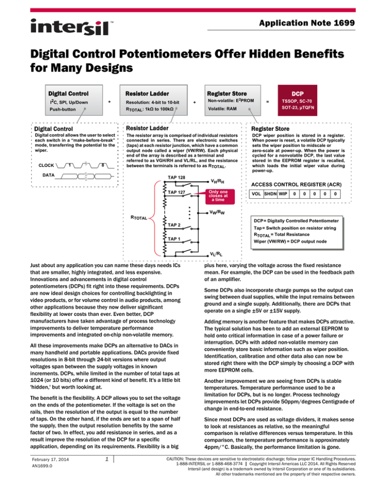
Resistor Ladder
Register Store
Digital control allows the user to select
each switch in a “make-before-break”
mode, transferring the potential to the
wiper.
The resistor array is comprised of individual resistors
connected in series. There are electronic switches
(taps) at each resistor junction, which have a common
output node called a wiper (VW/RW). Each physical
end of the array is described as a terminal and
referred to as VGH/RH and VL/RL, and the resistance
between the terminals is referred to as RTOTAL.
DCP wiper position is stored in a register.
When power is reset, a volatile DCP typically
sets the wiper position to midscale or
zero-scale at power-up. When the power is
cycled for a nonvolatile DCP, the last value
stored in the EEPROM register is recalled,
which loads the initial wiper value during
power-up.
CLOCK
1
8
DATA
TAP 128
TAP 127
VH/RH
Only one
closes at
a time
ACCESS CONTROL REGISTER (ACR)
VOL SHDN WIP
0
0
0
0
0
VW/RW
RTOTAL
DCP = Digitally Controlled Potentiometer
TAP 2
Tap = Switch position on resistor string
RTOTAL = Total Resistance
TAP 1
Wiper (VW/RW) = DCP output node
VL/RL
Just about any application you can name these days needs ICs
that are smaller, highly integrated, and less expensive.
Innovations and advancements in digital control
potentiometers (DCPs) fit right into these requirements. DCPs
are now ideal design choices for controlling backlighting in
video products, or for volume control in audio products, among
other applications because they now deliver significant
flexibility at lower costs than ever. Even better, DCP
manufacturers have taken advantage of process technology
improvements to deliver temperature performance
improvements and integrated on-chip non-volatile memory.
All these improvements make DCPs an alternative to DACs in
many handheld and portable applications. DACs provide fixed
resolutions in 8-bit through 24-bit versions where output
voltages span between the supply voltages in known
increments. DCPs, while limited in the number of total taps at
1024 (or 10 bits) offer a different kind of benefit. It's a little bit
'hidden,' but worth looking at.
The benefit is the flexibility. A DCP allows you to set the voltage
on the ends of the potentiometer. If the voltage is set on the
rails, then the resolution of the output is equal to the number
of taps. On the other hand, if the ends are set to a span of half
the supply, then the output resolution benefits by the same
factor of two. In effect, you add resistance in series, and as a
result improve the resolution of the DCP for a specific
application, depending on its requirements. Flexibility is a big
February 17, 2014
AN1699.0
1
plus here, varying the voltage across the fixed resistance
mean. For example, the DCP can be used in the feedback path
of an amplifier.
Some DCPs also incorporate charge pumps so the output can
swing between dual supplies, while the input remains between
ground and a single supply. Additionally, there are DCPs that
operate on a single ±5V or ±15V supply.
Adding memory is another feature that makes DCPs attractive.
The typical solution has been to add an external EEPROM to
hold onto critical information in case of a power failure or
interruption. DCPs with added non-volatile memory can
conveniently store basic information such as wiper position.
Identification, calibration and other data also can now be
stored right there with the DCP simply by choosing a DCP with
more EEPROM cells.
Another improvement we are seeing from DCPs is stable
temperatures. Temperature performance used to be a
limitation for DCPs, but is no longer. Process technology
improvements let DCPs provide 50ppm/degrees Centigrade of
change in end-to-end resistance.
Since most DCPs are used as voltage dividers, it makes sense
to look at resistances as relative, so the meaningful
comparison is relative differences versus temperature. In this
comparison, the temperature performance is approximately
4ppm/°C. Basically, the performance limitation is gone.
CAUTION: These devices are sensitive to electrostatic discharge; follow proper IC Handling Procedures.
1-888-INTERSIL or 1-888-468-3774 | Copyright Intersil Americas LLC 2014. All Rights Reserved
Intersil (and design) is a trademark owned by Intersil Corporation or one of its subsidiaries.
All other trademarks mentioned are the property of their respective owners.
Application Note 1699
As DCP features have improved, designers of consumer
electronics equipment or telecommunications systems have
been able to consider using DCPs in place of DACs. The decision
involves comparing the temperature performance, memory (or
lack of it), and flexibility, or rigidity, of a DCP compared with a
DAC. Those comparisons are blurring now that the performance
of DCPs is improving so much. For example, both provide linear
steps, but the DCP also can use logarithmic steps, therefore it's
an excellent choice for an application like an audio system.
Secondly, outputs of either DACs or DCPs can be found with an
output buffer to drive impedance loads, but it's more usual to
find a DCP with a simple resistance at the output.
DACs do have some fundamental advantages in some
applications, where absolute precision is an overarching
objective. DCPs can store their own calibration information,
directly set the gate bias for proper functioning in an application
like a base station, and dynamically adjust to include data from
other sources, such as temperature sensors.
Top uses for DCPs now: in pressure, temperature and laser
sensors; to trim voltages on voltage regulators; in power supply
modules to regulate voltage; and for adjusting analog signals for
digital systems.
Control interfaces are another issue. A DCP can provide
push-button controls or up-down controls, I2C and/or SPI
interfaces, whereas DACs typically only support serial and
parallel inputs.
Intersil Corporation reserves the right to make changes in circuit design, software and/or specifications at any time without notice. Accordingly, the reader is
cautioned to verify that the Application Note or Technical Brief is current before proceeding.
For information regarding Intersil Corporation and its products, see www.intersil.com
2
AN1699.0
February 17, 2014


