INTRODUCTION
With SCSI Card 2940U2W, you can connect up to 15 SCSI peripherals,
such as hard disk drives, scanners, CD-ROM drives, tape drives, to any
IBM-compatible computer with PCI expansion slots.
This installation guide provides instructions for:
• Installing the SCSI Card 2940U2W
• Connecting SCSI peripherals
• Installing SCSI Card 2940U2W software
See the SCSI Card 2940U2W User’s Reference for additional information on using the SCSI Card 2940U2W.
Check the Kit Contents
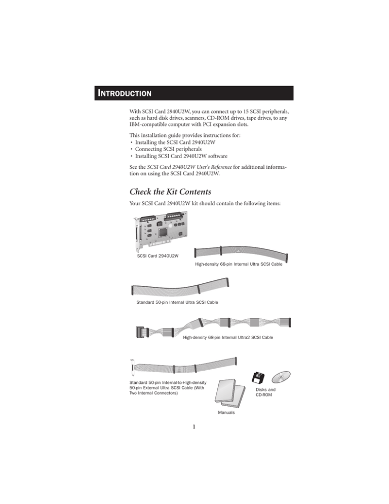
Your SCSI Card 2940U2W kit should contain the following items:
SCSI Card 2940U2W
High-density 68-pin Internal Ultra SCSI Cable
Standard 50-pin Internal Ultra SCSI Cable
High-density 68-pin Internal Ultra2 SCSI Cable
Standard 50-pin Internal-to-High-density
50-pin External Ultra SCSI Cable (With
Two Internal Connectors)
Disks and
CD-ROM
Manuals
1
Bus Segments on the SCSI Card 2940U2W
The SCSI Card 2940U2W features Adaptec SpeedFlex™ technology.
SpeedFlex technology ensures that you get the most performance from
your Ultra2 SCSI peripherals by electronically isolating the Ultra2 SCSI
segment from the Ultra SCSI segment on the SCSI bus. With the
SpeedFlex advantage, the SCSI Card 2940U2W can support Ultra2
SCSI peripherals at speeds up to 80 MBytes/sec while simultaneously
supporting Wide Ultra/Ultra (legacy) peripherals at speeds up to 40
MBytes/sec.
68-pin Internal
Ultra2 Connector
68-pin Internal
Wide Ultra Connector
50-pin Internal
Ultra Connector
AIC-3860
68-pin External
Ultra2 Connector
Ultra2 SCSI
Segment
Ultra SCSI
Segment
AIC-7890
NOTE
Attaching Wide Ultra/Ultra SCSI peripherals to the Ultra2
SCSI segment of the SCSI bus causes the Ultra2 SCSI segment and
any attached peripherals to drop to Ultra SCSI performance levels
(40 MBytes/sec). Attaching only Ultra2 peripherals to the Ultra2
segment, ensures that all peripherals on the Ultra2 segment will
perform at Ultra2 performance levels (80 MBytes/sec).
Attaching an Ultra2 peripheral to the Ultra SCSI segment causes the
Ultra2 peripheral to drop to Ultra SCSI performance levels instead
of Ultra2 SCSI performance levels at which it is designed to run.
2
INSTALLING
STEP 1
THE
SCSI CARD 2940U2W
Discharge any static electricity build-up before handling your SCSI
card by touching a grounded metal object (like the exposed metal
parts on the back of your computer).
WARNING Turn OFF power to the computer and disconnect the
power cord.
STEP 2
After you turn off your computer and unplug the power cord, remove
the cover from the computer.
Refer to your computer manual for instructions on removing the cover.
STEP 3
Locate an unused PCI expansion
slot and remove the expansion slot
cover. (The expansion slot must be
PCI Rev. 2.1 or higher compliant
and support Bus Mastering.) Save
the slot cover screw for use in
Step 4.
Computers may have
vertical or horizontal
expansion slots. Refer
to your computer
manual to locate the
PCI slots. If your
computer is a tower
model, lay it on its
side to allow for easier
installation of the
SCSI Card 2940U2W.
Slot Cover Screw
Expansion
Slot Cover
PCI Expansion Slots
(Typically White or Ivory)
3
STEP 4
Insert the SCSI Card 2940U2W into the PCI expansion slot; press
down firmly until it clicks into place, then replace the slot cover screw.
SCSI Card 2940U2W Installed
in a PCI Expansion Slot
SETTING UP SCSI PERIPHERALS
Setting up SCSI peripherals before attaching them to the SCSI Card
2940U2W typically involves setting SCSI IDs and termination, mounting internal peripherals inside your computer, and connecting power
cables to each peripheral. Since setup can vary from peripheral to
peripheral, always refer to the peripheral’s documentation for specific
instructions. Below are some guidelines for setting SCSI IDs and termination on your peripherals.
NOTE If you refer to the peripheral’s documentation for installation instructions, be sure to return to this document to continue
with installation of the software included in the package.
Check the SCSI IDs
The SCSI Card 2940U2W and each peripheral you connect to it
requires a unique SCSI ID number ranging from 0 to 15. ID numbers
don’t have to be sequential, as long as the SCSI Card 2940U2W and
each peripheral has a different number.
The SCSI Card 2940U2W is preset to ID 7 and should not be changed.
If you will be booting from a SCSI hard disk, it’s best to set the disk’s ID
at 0 or 1. Most SCSI hard disks come from the factory preset to ID 0.
The IDs for internal peripherals are usually set with jumpers; external
peripherals are usually set with a switch on the back of the peripheral.
Terminate the Ends
To ensure reliable communication on the SCSI bus, the peripheral at
the end of each cable, or the end of the cable itself, must have a terminator installed (or enabled). The peripherals between the ends of each
cable must have the terminator removed (or disabled).
4
CONNECTING SCSI PERIPHERALS
A total of 15 SCSI peripherals can be connected to the SCSI Card
2940U2W. Before connecting peripherals to the SCSI Card 2940U2W,
be sure to also review Setting Up SCSI Peripherals on page 3.
68-pin Internal Ultra2 SCSI Connector
Use the 68-pin internal Ultra2 SCSI connector to connect internal
Ultra2 peripherals. The connector is an Ultra2 Low Voltage
Differential, Single Ended (Ultra2-LVD/SE) connector. The internal
Ultra2 cable included in the kit allows up to four internal Ultra2
peripherals. If you have more than four Ultra2 peripherals, you will
need to obtain an Ultra2 cable with enough connectors to accommodate all of your Ultra2 peripherals. Follow these steps to connect your
internal Ultra2 peripherals:
NOTE
We recommend keeping your Ultra2 peripherals separate
from your non-Ultra2 peripherals. Connecting a non-Ultra2
peripheral to the Ultra2 SCSI connector forces the Ultra2 SCSI segment and any attached peripherals to drop down to Ultra SCSI performance levels (40 MBytes/sec). (See “Bus Segments on the SCSI
Card 2940U2W” on page 2.)
STEP 1
Locate the 68-pin internal Ultra2 SCSI cable in the package.
Connect to
SCSI Card 2940U2W
Connect to Ultra2 Peripherals
Built-in Terminator
STEP 2
Plug the long end of the cable to the Ultra2 connector on the SCSI
Card 2940U2W (connectors are labeled “Ultra2-LVD/SE”).
Connectors Labeled
“Ultra2-LVD/SE”
68-pin Internal Ultra2
SCSI Connector
68-pin Internal Ultra2 SCSI Cable
5
STEP 3
Plug the remaining connectors to your internal Ultra2 SCSI peripherals.
Ultra2 SCSI Peripherals (Ultra2-LVD/SE)
Built-in Terminator on Cable
NOTE
Internal Ultra2 SCSI peripherals come from the factory
with termination disabled and cannot be changed. Proper termination is provided by the built-in terminator at the end of the Ultra2
internal SCSI cable provided in the kit.
68-pin Internal Wide Ultra SCSI Connector
Use the 68-pin internal Wide Ultra SCSI connector to connect internal
Fast/Wide Ultra SCSI peripherals that have 68-pin connectors. Do not
connect Ultra2 peripherals to this connector.
The 68-pin internal Ultra SCSI cable included in the kit allows you to
to connect up to two Fast/Wide Ultra peripherals. If you have more
than two Fast/Wide Ultra peripherals, you will need to obtain a 68-pin
cable with enough connectors to accommodate all of your Fast/Wide
Ultra peripherals. Follow these steps to connect your internal
Fast/Wide Ultra peripherals.
STEP 1
Locate the 68-pin internal Ultra SCSI cable in the package.
Connect to Fast/Wide Ultra
Peripheral (Terminated)
Connect to SCSI Card 2940U2W
Connect to Fast/Wide Ultra
Peripheral (Not Terminated)
6
STEP 2
Plug the long end of the cable to the 68-pin internal Ultra SCSI
connector on the SCSI Card 2940U2W.
68-pin Internal Wide Ultra SCSI Cable
68-pin Internal Wide Ultra SCSI Connector
STEP 3
STEP 4
Plug the other end of the cable to a terminated Fast/Wide Ultra SCSI
peripheral.
To connect a second Fast/Wide Ultra
SCSI peripheral, plug the middle
connector of the cable to the
peripheral. The peripheral must
not be terminated.
Unterminated SCSI Peripheral
Terminated SCSI Peripheral
50-pin Internal Ultra SCSI Connector
Use the 50-pin internal Ultra SCSI connector to connect internal or
external Fast/Ultra Narrow SCSI peripherals that have standard 50-pin
connectors.
Internal Fast/Ultra Narrow SCSI Peripherals
The 50-pin internal cable included in the kit allows you to connect up
to two standard internal SCSI peripherals. If you have more than two
standard internal 50-pin peripherals, you will need to obtain a 50-pin
cable with enough connectors to accommodate all of your standard
peripherals. Follow these steps to connect your standard internal
Fast/Ultra Narrow peripherals:
STEP 1
Locate the 50-pin internal Ultra SCSI cable in the package.
Connect to SCSI Card 2940U2W
Connect to Fast/Ultra Narrow
Peripheral (Terminated)
Connect to Fast/Ultra Narrow
Peripheral (Not terminated)
(Continued on the other side)
7
STEP 2
Plug the long end of the cable to the 50-pin connector on the SCSI
Card 2940U2W.
50-pin Internal Ultra SCSI Connector
50-pin Internal Ultra SCSI Cable
STEP 3
STEP 4
Plug the other end of the cable to a terminated Fast/Ultra
Narrow SCSI peripheral.
To connect a second Fast/Ultra Narrow
SCSI peripheral, plug the middle
connector of the cable to the
peripheral. The peripheral must
not be terminated.
Unterminated SCSI Peripheral
Terminated SCSI Peripheral
External Fast/Ultra Narrow SCSI Peripherals
The 50-pin internal-to-high-density 50-pin external Ultra SCSI cable,
also included in the kit, allows you to connect your standard external
SCSI peripherals and up to two standard internal SCSI peripherals. For
each external peripheral, you will need to obtain a 50-pin external SCSI
cable. Follow these steps to connect your standard external peripherals:
NOTE
This cable enables you to keep external Ultra SCSI peripherals without impeding the performance of your Ultra2 SCSI
peripherals. (See “Bus Segments on the SCSI Card 2940U2W” on
page 2.)
STEP 1
Locate the 50-pin internal-to-high-density 50-pin external Ultra SCSI
cable in the package.
Connect to SCSI Card 2940U2W
Secure to Card Slot Opening in
Computer Chassis
Connect to Fast/Ultra Narrow Internal
Peripherals (Not terminated)
8
STEP 2
Remove an available slot cover from the chassis of the computer.
Remove Slot Cover (Preferably
Next to the SCSI Card 2940U2W)
STEP 3
Plug one end of the cable to the 50-pin internal Ultra SCSI connector
on the SCSI Card 2940U2W.
50-pin Internal Ultra SCSI Connector
Standard 50-pin Internal-to-High-density
50-pin External Ultra SCSI Cable
STEP 4
Secure the mounting bracket of the cable to the exposed card slot
opening in the chassis of the computer.
Use these connectors on the cable to
connect up to two internal Fast/Ultra
Narrow SCSI peripherals, These
peripherals must not be terminated.
9
STEP 5
Connect one end of the external
SCSI cable to the 50-pin external
connector on the internal-toexternal cable.
High-density 50-pin
External SCSI Cable
(Not Included in Kit)
68-pin External Ultra2 SCSI Connector
High-density 50-pin External Connector
STEP 6
Connect the other end of the external SCSI cable to a SCSI connector
on the back of the external SCSI
peripheral. If you are installing
only one external peripheral, terminate the peripheral and
skip to Step 8.
4
SCSI Terminator
(Not Included in Kit)
4
STEP 7
Connect other external peripherals by connecting each peripheral to
the previous one until all peripherals are connected. The peripheral at
the end of the chain must be the only external peripheral terminated.
Terminated SCSI
Peripheral
STEP 8
Connect all power cables to the external peripherals.
10
NOTE
When using the internal-to-external Ultra SCSI cable, the
50-pin external connector itself, or the last external peripheral connected to the connector, must have a SCSI terminator installed.
Terminate Here
Terminate Here
WRONG!
Not Terminated Here
68-pin External Ultra2 SCSI Connector
Use the 68-pin external Ultra2 SCSI connector to connect your external Ultra2 peripherals. Ultra2 external cables are not included in the
kit. For each external Ultra2 peripheral, you will need to obtain a 68pin external Ultra2 SCSI cable. Follow these steps to connect your
external Ultra2 SCSI peripherals:
NOTE
We recommend keeping your Ultra2 peripherals separate
from your non-Ultra2 peripherals. Connecting a non-Ultra2
peripheral to the Ultra2 SCSI connector forces the Ultra2 SCSI segment and any attached peripherals to drop down to Ultra SCSI
performance levels (40 MBytes/sec). (See “Bus Segments on the
SCSI Card 2940U2W” on page 2.)
STEP 1
Connect one end of the external SCSI cable to the external Ultra2 connector on the SCSI Card 2940U2W.
High-density 68-pin
External Ultra2 SCSI Cable
(Not Included in Kit)
68-pin External Ultra2
SCSI Connector
11
STEP 2
Connect the other end of the cable
to a SCSI connector on the back
of an external peripheral. If you
are installing only one external
peripheral, terminate the
peripheral and skip to
Step 4.
4
SCSI Terminator
(Not Included in Kit)
4
STEP 3
Connect other external peripherals by connecting each peripheral to
the previous one until all peripherals are connected.
The peripheral at the end of the chain must
be the only external peripheral terminated.
Terminated SCSI
Peripheral
STEP 4
Connect all power cables to
the external peripherals.
INSTALLING SCSI CARD 2940U2W SOFTWARE
To install the SCSI Card 2940U2W software (software driver), go to
the section below for the operating system (for example, Windows®
95) installed on your computer. If the operating system is not yet
installed, install it now. Refer to your operating system documentation
for instructions.
NOTE If you have installed a new SCSI hard drive in a computer
running Windows or DOS, you must partition and format the drive
with the DOS Fdisk and Format commands before it can be used.
Refer to your Windows and DOS documentation for instructions.
12
Computers with Windows 95
STEP 1
Turn on all external peripherals and then the computer. Windows 95
now will recognize the SCSI Card 2940U2W installed in your computer and will ask you to select which driver you want to install.
STEP 2
Select “Driver from disk provided by hardware manufacturer,” then
click OK.
STEP 3
Insert the Adaptec EZ-SCSI Setup Diskette in your floppy disk drive,
then click OK.
STEP 4
Follow the instructions that appear onscreen.
Computers with Windows NT
STEP 1
STEP 2
STEP 3
STEP 4
STEP 5
STEP 6
Turn on all external peripherals and then the computer.
Start Windows NT on your computer.
Insert the Adaptec EZ-SCSI Setup Diskette in your floppy disk drive.
Click the Start button, then click Run.
When the Run dialog box appears, type a:\setup if you are using the A
drive, or b:\setup if you are using the B drive. Then click OK.
Follow the instructions that appear onscreen.
Computers with NetWare, OS/2, SCO UNIX,
and UnixWare
The Adaptec 7800 Family Manager Set included in the package allows
you to install drivers for NetWare, OS/2, SCO UNIX, and UnixWare.
Refer to the 7800 Family Manager Set User’s Guide for installation
instructions.
R
We move the information that
moves your world.™
© 1997, Adaptec, Inc. All rights reserved.
Printed in Singapore
Stock No.: 511794-00, Rev. A RQ 12/97
13
ADAP TEC
INSTALLATION
GUIDE
SCSI CARD 2940U2W


