Glass Break Detector
Battery Installation & Replacement
2GIG-GB1-345
Remove the cover by twisting counterclockwise. Use only the recommended replacement batteries (see Specifications). Be sure to
observe the polarity.
Operating Instructions
WARNING! The polarity of the battery must be observed, as shown (See Figure 4).
Improper handling of lithium batteries may result in heat generation, explosion or
fire, which may lead to personal injuries. Replace only with the same or equivalent
type of battery as recommended by the manufacturer. (see Specifications)
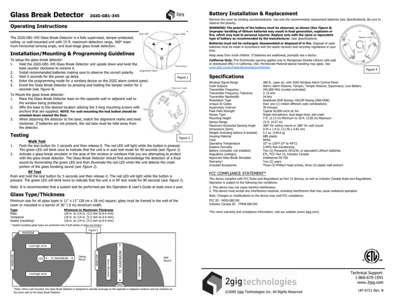
The 2GIG-GB1-345 Glass Break Detector is a fully supervised, tamper-protected,
ceiling- or wall-mounted unit with 15 ft. maximum detection range, 360° maximum horizontal sensing angle, and dual-stage glass break detection.
Batteries must not be recharged, disassembled or disposed of in fire. Disposal of used
batteries must be made in accordance with the waste recovery and recycling regulations in your
area.
Installation/Mounting & Programming Guidelines
Keep away from small children. If batteries are swallowed, promptly see a doctor.
To setup the glass break detector:
1.
Hold the 2GIG-GB1-345 Glass Break Detector unit upside down and twist the
base counter clockwise to remove it.
2.
Install recommended batteries making sure to observe the correct polarity.
3.
Wait 5 seconds for the power up delay.
4.
Enter the programming mode for a wireless device on the 2GIG alarm control panel.
5.
Enroll the Glass Break Detector by pressing and holding the tamper switch for 2
seconds (see Figure 4).
California Only: This Perchlorate warning applies only to Manganese Dioxide Lithium cells sold
or distributed ONLY in California, USA. Perchlorate Material-special handling may apply. See
www.dtsc.ca.gov/hazardouswaste/perchlorate.
Figure 1
To Mount the glass break detector:
1.
Place the Glass Break Detector base on the opposite wall or adjacent wall to
the window being protected.
2.
Affix the base to the desired location utilizing the 3 long mounting screws with
anchors that are supplied. NOTE: For wall mounting the test button should be
oriented down nearest the floor.
3.
When attaching the detector to the base, match the alignment marks and twist
clockwise. If batteries are not present, the red tabs must be held away from
the detector.
Testing
1.
2.
Figure 2
Walk Test
Push the test button for 2 seconds and then release it. The red LED will light while the button is pressed.
The green LED will blink once to indicate that the unit is in auto test mode for 90 seconds (see Figure 1).
Activate a glass break simulator in the area of the window or windows that you are attempting to protect
with the glass break detector. The Glass Break Detector should first acknowledge the detection of a thud
sound by illuminating the green LED and then illuminate the red LED when the unit detects the crash
portion of the glass breaking sound (see Figure 1).
RF Test
Push and hold the test button for 5 seconds and then release it. The red LED will light while the button is
pressed. The green LED will blink twice to indicate that the unit is in RF test mode for 90 seconds (see Figure 1).
Note: It is recommended that a system test be performed per the Operation & User’s Guide at least once a year.
Specifications
Wireless Signal Range
Code Outputs
Transmitter Frequency
Transmitter Frequency Tolerance
Transmitter Bandwidth
Modulation Type
Unique ID Codes
Supervisory Interval
Peak Field Strength
Sensor Type
Mounting Height
Sensor Range
Maximum Horizontal Sensing Angle
Dimensions (DxH)
Weight (including battery & bracket)
Housing Material
Color
Operating Temperature
Relative Humidity
Battery (included, not installed)
Regulatory Listing(s)
Approved Glass Break Simulator
Warranty*
Included Accessories
300 ft., open air, with 2GIG Wireless Alarm Control Panel
Alarm; Alarm Restore; Tamper; Tamper Restore; Supervisory; Low Battery
345.000 MHz (crystal controlled)
± 15 kHz
24 kHz
Amplitude Shift Keying—On/Off Keying (ASK-OOK)
Over one (1) million different code combinations
70 minutes
Typical 50,000 uV/m at 3m
Single microphone, dual stage thud, and crash
7 ft. (2.13 m) Minimum to 10 ft. (3.05 m) Maximum
15 ft. (4.57 m)
360° for ceiling mount or 180° for wall mount
4.55 x 1.9 in. (11.56 x 4.83 cm)
5.1 oz. (144.6 g)
ABS plastic
White
32° to 120°F (0° to 49°C)
5-95% Non-Condensing
Two (2) Panasonic CR123A, or equivalent Lithium batteries
ETL, FCC Part 15, Industry Canada
Intellisense FG-701
Two (2) years
Three (3) Phillip’s head screws, three (3) plastic wall anchors
FCC COMPLIANCE STATEMENT*
This device complies with FCC Rules and Regulations as Part 15 devices, as well as Industry Canada Rules and Regulations.
Operation is subject to the following two conditions:
1. This device may not cause harmful interference.
2. This device must accept any interference received, including interference that may cause undesired operation.
Glass Type/Thickness
Note: Changes or modifications to the device may void FCC compliance.
Minimum size for all glass types is 11” x 11” (28 cm x 28 cm) square; glass must be framed in the wall of the
room or mounted in a barrier of 36” (.9 m) minimum width.
FCC ID: WDQ-GB1345
Industry Canada ID: 7794A-GB1345
Type
Plate
Tempered
Sealed Insulating†
Minimum to Maximum Thickness
1/8 in. to 1/4 in. (3.2 mm to 6.4 mm)
1/8 in. to 1/4 in. (3.2 mm to 6.4 mm)
1/8 in. to 1/4 in. (3.2 mm to 6.4 mm)
Figure 4
*For more warranty and compliance information, visit our website (www.2gig.com).
† Sealed insulating glass types are protected only if both plates of glass are broken.
Figure 3
Ceiling
Mount
Wall
Mount*
Technical Support:
1-866-670-1591
www.2gig.com
*Note: When wall mounted, the Glass Break Detector is designed to provide coverage on the opposite or adjacent windows and not windows on
the same wall as the Glass Break Detector.
©2009 2gig Technologies Inc. All Rights Reserved
187-0721 Rev. B


