1
TM
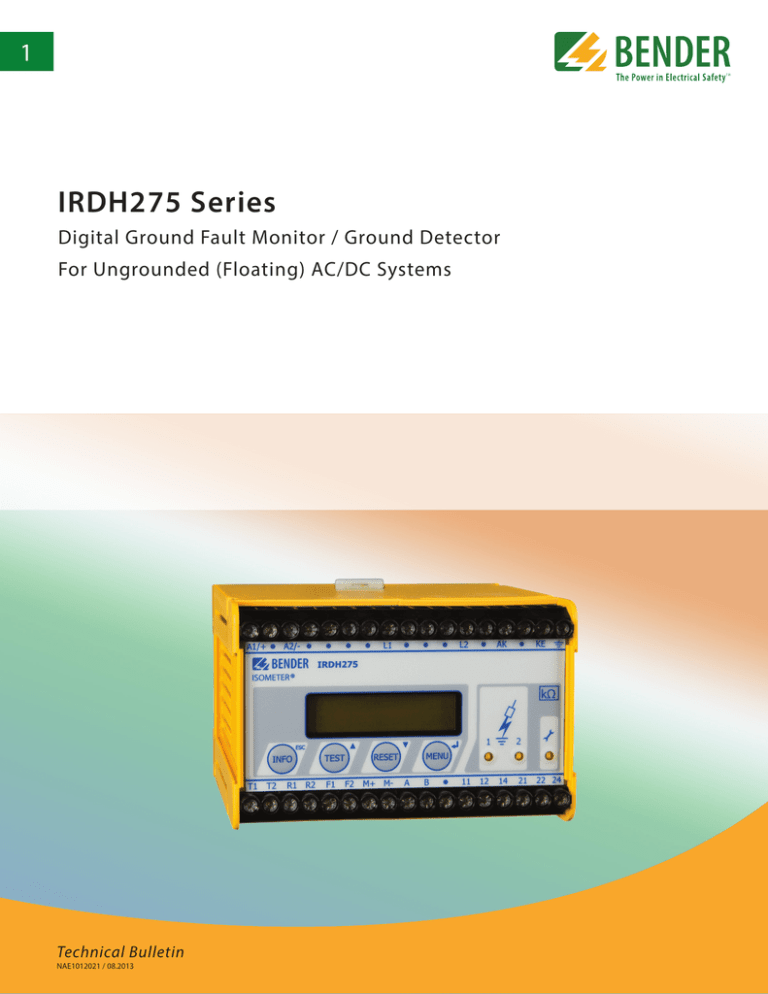
IRDH275 Series
Digital Ground Fault Monitor / Ground Detector
For Ungrounded (Floating) AC/DC Systems
Technical Bulletin
NAE1012021 / 08.2013
IRDH275 Series
Digital ground fault monitor / ground detector
For ungrounded (floating) AC/DC systems
Description
This device meets or exceeds the requirements of NEC 250.21(B) and CEC 10-106(2) for
ground detectors in ungrounded AC systems, as well as the upcoming 2014 requirement
of NEC 250.167(A) for ungrounded DC systems.
The IRDH275 monitors for ground faults in ungrounded single-phase AC, three-phase AC,
and DC systems by monitoring the system's insulation resistance. It may be connected to
systems of up to 793 VAC / 650 VDC. Voltage coupler accessories extend this range. The
AMP Plus measuring principle utilized by the IRDH275 meets the requirements of modern
power systems, including pure DC systems, systems with rectifiers, and systems with
variable frequency drives (VFDs). In systems with high leakage capacitances, the IRDH275
automatically adapts itself to ensure an accurate reading.
Features
The IRDH275 features a digital display showing the system's insulation resistance'in
real-time. All settings are changed via the device's built-in menu. The IRDH275 utilizes an
external supply voltage for power, which allows deenergized systems to also be monitored.
•
For a panel mounted version, please refer to the IRDH375.
IRDH275
Meets or exceeds requirements for
NEC 250.21(B) and CEC 10-106(2), as
well as the upcoming 2014 requirement of NEC 250.167(A)
•
Ground fault detection via insulation
monitoring for ungrounded AC/DC
systems, single-phase or three-phase
•
Works on systems up to 793 VAC / 650
VDC
•
Voltage ranges extendable up to 7200
VAC / 1760 VDC with voltage coupler
modules
•
Two separate adjustable response
values, 1 kΩ - 10 MΩ
•
Advanced measuring principle which
detects both AC and DC faults, symmetrical faults, automatically adapts
to high system leakage capacitances
When the insulation resistance from system to ground falls below the set response value,
the alarm relays switch and the alarm LEDs activate. Two separately adjustable alarmcontacts can be set to a prewarning and main warning alarm. The measured value is indicated on the LCD display or an externally connectable measuring instrument. A latching
setting ("fault memory") allows the device to reset automatically or require a manual reset. An external and internal test/reset can be activated remotely or on the device. A
comprehensive INFO menu displays additional information such as the system's leakage
capacitance.
The IRDH275 continuously monitors the equipment ground connection to ensure proper
operation. The device's easy-to-use onboard menu manages all settings via the detailed
LCD screen.
Additional Features
• History memory with real-time clock to store up to 300 timestamped event records
•Galvanically isolated RS-485 interface (BMS protocol) for data exchange with other
Bender devices and communication systems
•
Info button to display device settings
and system leakage capacitance
•Standby contacts and RS-485 communication for operating multiple ground fault detectors in systems tied together with tiebreakers or interlocks
•
Self monitoring
• Galvanically isolated analog output, 0(4 ) - 20 mA
•
Automatic self-test setting
•
Connection for external metering
Use in Interconnected Ungrounded Systems
•
Built-in and external test/reset
•
Two separate alarms with two voltagefree SPDT contacts
•
Normally energized (failsafe) or deenergized (non-failsafe) operation
•
Backlit LCD display
•
RS-485 interface
Approvals
2
Function
Only one BENDER insulation monitor may be active when several ungrounded systems
are coupled together via a tiebreaker or other means. The disconnect relays and control
inputs F1/F2 integrated into the IRDH275 guarantee no interference with other BENDER
devices when the system tiebreaker is closed. IRDH275B models feature automatic control via RS-485 with no control inputs necessary.
Measurement Method
The IRDH275 series uses the AMPPlus measuring principle. This measuring principle allows for the precise monitoring of modern power supply
systems, pure DC systems, systems where AC/DC rectification and power conversion may occur, systems with variable frequency drives (VFDs), and systems with high leakage capacitances.
Wiring
2
3
3Ø AC System
1
1Ø AC System
GND
5
Un
Un
DC System
Un
4
6
7
8
9
10
11
12
2 -Wiring diagram for a three-phase system. Only two connections to the system are necessary to monitor all three phases.
9 -IRDH275: Analog output, electrically isolated: 0 - 400 µA
IRDH275B: Analog output, electrically isolated:
0 - 20 mA or 4 - 20 mA
3
10 - RS-485 interface:
1 - External supply voltage used to power device
Wiring diagram for a single-phase system
4 -Wiring diagram for a DC system
5 -Equipment ground connections
6 - External test button (normally open contact)
7 -External reset button (normally closed contact). When the
terminals are open, the fault message will not be stored.
8 -Standby contact. When the contact is closed, no insulation
measurements take place.
IRDH275: One-way ASCII stream with measurement status
IRDH275B: Two-way communication with other BENDER devices, including communication gateways
11 - Alarm relay 1, normally energized or de energized contact
12 - Alarm relay 2/System Fault Relay, normally energized or de-
energized contact
Displays and Controls
1 -INFO key: displays pertinent system information
ESC key: Goes back a step inside device's menu
2 -TEST button: Activates self-test
Arrow up key: Scrolls up inside device's menu
3 - LCD display
4 -RESET button: Resets device
Arrow down key: Scrolls down inside device's menu
5 -MENU key: Activates device's internal menu
Enter key: Confirm change inside device's menu
1
2 3 4
5
6 7 8
6 - Alarm LED 1 lights: Alarm, Prealarm
7 - Alarm LED 2 lights: Alarm, Main alarm
8 - System fault LED: Lights on connection or device error
3
Wiring diagrams – Connecting to voltage couplers
IRDH275 with voltage coupler AGH150W-4
IRDH275 with voltage coupler AGH204S-4
1
2
Un
Un 0 - 1760 VDC
GND
GND
1 - without rectifiers Un = 3AC 0 - 1650 V (DC max. 1000 V)
2 - with rectifiersUn = 3AC 0 - 1300 V (peak voltage downstream of the rectifier or intermediate
voltage max. 1840 V)
Sample Response Times
IRDH275 with voltage coupler AGH520S
Three-phase 0 - 7200 VAC (50 - 400 Hz)
2
AGH520S
5
4
3
GND
4
Response times in relation to the system leakage
capacitances: Ce = 1 - 500 µF, Un = 0 - 793 V/50 Hz
Ordering Information
1)
RS-485 interface
Analog Output
One-way
ASCII string
0 - 400 µA
Proprietary 2-way
protocol
0(4) - 20 mA
Supply voltage US1)
AC
88 - 264 V (42 - 460 Hz)
–
–
88 - 264 V (42 - 460 Hz)
–
–
DC
77 - 286 V
19.2 - 72 V
10.2 - 36 V
77 - 286 V
19.2 - 72 V
10.2 - 36 V
Type
Ordering No.
IRDH275-435
IRDH275-427
IRDH275-425
IRDH275B-435
IRDH275B-427
IRDH275B-425
B 9106 5100
B 9106 5104
B 9106 5108
B 9106 5101
B 9106 5105
B 9106 5109
Absolute values
All versions support adding option “W” (added to the end of the part number), adding additional shock/vibration protection and wider
temperature range.
Accessories
Dimensions
Dimensions in inches (mm)
Voltage couplers
Ordering No.
7204-1421
9604-1421
9620-1421
AGH150W-4
AGH204S-4
AGH520S
B 986 763
B 986 764
B 986 841
B 9801 8006
B 914 013
B 914 033
4.4” (112.5)
4.1”
(105)
4.1”
(105)
Ø 0.18”
(4.5)
2.9” (74)
External meters
Type
3.2” (81)
Description
5
Technical data
Insulation coordination acc. to IEC 60664-1
Rated insulation voltage
Rated impulse voltage/pollution degree
Voltage ranges
Nominal system voltage Un
Rated frequency fn
Supply voltage US
Frequency range US Power consumption
AC 800 V
8 kV/3
AC, 3(N)AC 0 - 793 V, DC 0 - 650 V
DC, 0.2 - 460 Hz
AC 88 - 264 V, DC 77 - 286 V
20 - 460 Hz
≤ 14 VA
Response values
Response value Ran1 (Alarm 1)
1 kΩ - 10 MΩ
Response value Ran2 (Alarm 2)
1 kΩ - 10 MΩ
Absolute error (1 kΩ - 10 kΩ) + 2 kΩ
Relative percentage error (10 kΩ - 10 MΩ)
0 % - + 20 %
Response time tan at RF = 0.5 x Ran and Ce = 1 µF
<5s
Measuring time
see characteristic curves (TGH page 69)
Hysteresis (1 kΩ - 10 kΩ)/(10 kΩ - 10 MΩ)
+ 2 kΩ/25 %
Measuring circuit
Measuring voltage Um (peak value)
Measuring current Im (at RF = 0 Ω)
Internal DC resistance Ri
Impedance Zi at 50 Hz
Permissible extraneous DC voltage Ufg
Permissible system leakage capacitance Factory setting
Displays
Display (illuminated)
Characters (number of characters, height)
Display range, measuring value
Absolute error (1 kΩ - 10 kΩ)
Relative percentage error (10 kΩ - 10 MΩ)
Outputs
Test/reset button
Current output measuring instrument
Load
Load B version
6
± 50 V
≤ 278 µA
≥ 180 kΩ
≥ 180 kΩ
≤ 1200 V
≤ 500 μF
150 µF
two-line display
2 x 16 characters/4 mm
1 kΩ - 10 MΩ
± 1 kΩ
± 10 %
internal/external
120 kΩ
≤ 400 µA (12.5 kΩ)
≤ 20 mA (500 Ω)
Serial interfaces
IRDH275RS-485/ASCII
IRDH275BRS-485/BMS
Max. cable length
3900 ft
Recommended cable (shielded, shield on one side connected to ground)
J-Y(ST)Y 2 x 0.6
Terminating resistor
120 Ω (0.5 W)
Switching elements
Number of switching elements 2 SPDT contacts
Operating principle
normally energized/de energized operation
Factory setting
normally de energized operation
Electrical service life, number of cycles
12000
Contact classIIB in accordance with DIN IEC 60255-0-20
Rated contact voltage
AC 250 V/DC 300 V
Making capacity
AC/DC 5 A
Breaking capacity
2 A, AC 230 V, PF = 0.4 – 0.2 A, DC 220 V, L/R = 0.04 s
Minimum contact current at DC 24 V
2 mA (50 mW)
General data
Shock resistance IEC 60068-2-27 (during operation)
15 g/11 ms
Bumping IEC 60068-2-29 (during transport)
40 g/6 ms
Vibration resistance IEC 60068-2-6 (during operation)
1 g/10 - 150 Hz
Vibration resistance IEC 60068-2-6 (during transport)
2 g/10 - 150 Hz
Ambient temperature (during operation/during storage)
- 10 °C - + 55 °C/- 40 °C - + 70 °C
Climatic class acc. to DIN IEC 60721-3-3
3K5
Operating mode
continuous operation
Mounting display oriented
Connection
screw-type terminals
Connection properties rigid/flexible
AWG 24...12 / 24...14
Degree of protection, internal components /terminal (DIN EN 60529) IP30 / IP20, NEMA 1
DIN rail mounting acc. to
DIN EN 60715/IEC 60715
Screw mounting, mounting plate
2 x M4
Flammability class
UL94V-0
Product standards
DIN EN 61557-8: 1998-05
EN 61557-8: 1997-03, IEC 61557-8: 1997-02
ASTM F1669M-96, ASTM F1207M-96
Operating manual
TGH1361
Weight
approx. 1.1 lb
Option “W”
Shock resistance IEC 60068-2-27 (during operation)
Bumping IEC 60068-2-29 (during transport)
Vibration resistance IEC 60068-2-6
Ambient temperature (during operation)
Ambient temperature (during transport)
30 g/11 ms
40 g/6 ms
1.6 mm/10 - 25 Hz, 4 g/25 - 150 Hz
- 40 °C - + 70 °C
- 40 °C - + 85 °C
Document NAE1012021 / 08.2013 / © Bender Inc. All Rights Reserved.
TM
USA • Coatesville, PA
Toll-Free: 800-356-4266 • Main: 610-383-9200
Fax: 610-383-7100 • E-mail: info@bender.org
Canada • Mississauga, ON
Toll-Free: 800-243-2438 • Main: 905-602-9990
Fax: 905-602-9960 • E-mail: info@bender-ca.com
bender.org • bender.org/mobile


