DATASHEET
PDM option for APx
Built-in PDM interface for APx audio analyzers
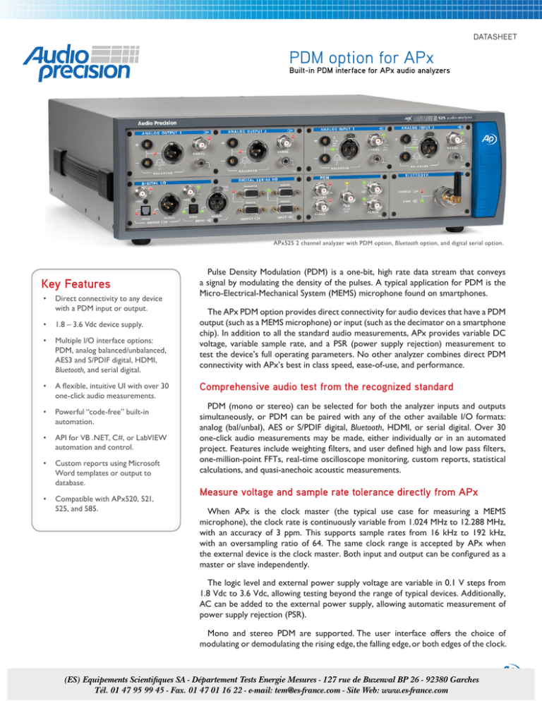
APx525 2 channel analyzer with PDM option, Bluetooth option, and digital serial option.
Key Features
• Direct connectivity to any device
with a PDM input or output.
• 1.8 – 3.6 Vdc device supply.
• Multiple I/O interface options:
PDM, analog balanced/unbalanced,
AES3 and S/PDIF digital, HDMI,
Bluetooth, and serial digital.
• A flexible, intuitive UI with over 30
one-click audio measurements.
• Powerful “code-free” built-in
automation.
• API for VB .NET, C#, or LabVIEW
automation and control.
• Custom reports using Microsoft
Word templates or output to
database.
• Compatible with APx520, 521, 525, and 585.
Pulse Density Modulation (PDM) is a one-bit, high rate data stream that conveys
a signal by modulating the density of the pulses. A typical application for PDM is the
Micro-Electrical-Mechanical System (MEMS) microphone found on smartphones.
The APx PDM option provides direct connectivity for audio devices that have a PDM
output (such as a MEMS microphone) or input (such as the decimator on a smartphone chip). In addition to all the standard audio measurements, APx provides variable DC
voltage, variable sample rate, and a PSR (power supply rejection) measurement to
test the device’s full operating parameters. No other analyzer combines direct PDM
connectivity with APx’s best in class speed, ease-of-use, and performance.
Comprehensive audio test from the recognized standard
PDM (mono or stereo) can be selected for both the analyzer inputs and outputs
simultaneously, or PDM can be paired with any of the other available I/O formats:
analog (bal/unbal), AES or S/PDIF digital, Bluetooth, HDMI, or serial digital. Over 30
one-click audio measurements may be made, either individually or in an automated
project. Features include weighting filters, and user defined high and low pass filters,
one-million-point FFTs, real-time oscilloscope monitoring, custom reports, statistical
calculations, and quasi-anechoic acoustic measurements.
Measure voltage and sample rate tolerance directly from APx
When APx is the clock master (the typical use case for measuring a MEMS
microphone), the clock rate is continuously variable from 1.024 MHz to 12.288 MHz,
with an accuracy of 3 ppm. This supports sample rates from 16 kHz to 192 kHz,
with an oversampling ratio of 64. The same clock range is accepted by APx when
the external device is the clock master. Both input and output can be configured as a
master or slave independently.
The logic level and external power supply voltage are variable in 0.1 V steps from
1.8 Vdc to 3.6 Vdc, allowing testing beyond the range of typical devices. Additionally,
AC can be added to the external power supply, allowing automatic measurement of
power supply rejection (PSR).
Mono and stereo PDM are supported. The user interface offers the choice of
modulating or demodulating the rising edge, the falling edge, or both edges of the clock.
>
ap.com/products/apx/pdm
(ES) Equipements Scientifiques SA - Département Tests Energie Mesures - 127 rue de Buzenval BP 26 - 92380 Garches
Tél. 01 47 95 99 45 - Fax. 01 47 01 16 22 - e-mail: tem@es-france.com - Site Web: www.es-france.com
PSR measurements
Because APx can modulate the DC voltage
supplied to the device under test, the analyzer
is able to measure power supply rejection ratio
and PSR vs frequency.
FAST & INTUITIVE UI
A test engineer measures the PSRR of a MEMS microphone. If desired, the result could be added to a
larger automated sequence of measurements and then output to a formatted Word doc or a database.
Modulator maximum input level
Master clock range
SNR
1.024 MHz to 12.288 MHz
109 dB (1 kHz, 20 kHz BW, unwtd)
Oversampling ratio
THD+N
16 kHz to 192 kHz
Automation and sharing data
PDM Specs
Complex test sequences can be created within
the UI, or the APx API can be accessed for full
control from any .NET application or LabVIEW.
Graph results are stored within the project,
and projects can be locked before sharing with
contract manufacturers or other partners.
Sample rate range
–6 dBFS
64
Interface logic levels
–107 dB (1 kHz, –6 dBFS, 20 kHz BW,
unwtd))
Edge modes
–116 dB (1 kHz, –6 dBFS)
1.8 – 3.6 V
Rising edge, I channel; Falling edge, 1
channel; Stereo (Both edges), 2 channel
Flatness
DC output
Connectors
APx500 Series Audio Analyzer Key Specifications
Most PDM devices have PDM at one end of
the audio chain and a transducer at the other. APx’s Acoustic Response measurement provides
14 key acoustic results in 3 seconds, with an
energy time curve display provided to find the
ideal time gate quickly and easily.
Output data, output clock, input data, input
clock, external power (all via BNC)
SYSTEM PERFORMANCE ANALYZER PERFORMANCE
Residual THD+N (20 kHz BW)
Maximum Rated Input Voltage
GENERATOR PERFORMANCE Maximum Bandwidth
Sine Frequency Range
IMD Measurement Capability
–105 dB + 1.3 µV [APx520-25] –103 dB + 1.4 µV [APx585]
0.1 Hz to 80.1 kHz [APx520-25] 5 Hz to 80.1 kHz [APx585]
Frequency Accuracy
2 ppm [APx520-25] 3 ppm [APx585]
XII0118153800
300 Vrms (bal) / 160 Vrms (unbal)
[APx520-25] 110 Vrms (bal/unbal) [APx585]
>90 kHz
SMPTE, MOD, DFD
Amplitude Accuracy (1 kHz)
±0.05 dB
Amplitude Flatness (20 Hz–20 kHz)
±0.008 dB
IMD Test Signals
Residual Input Noise (20 kHz BW)
SMPTE, MOD, DFD
Maximum Amplitude (balanced)
1.3 µV
21.21 Vrms [APx520-25] 14.4 Vrms [APx585]
Individual Harmonic Analyzer
Amplitude Accuracy
Max FFT Length
Flatness (20 Hz–20 kHz)
DC Voltage Measurement
±0.05 dB
±0.008 dB
d2–d10
1024K points
Yes
Analog Output Configurations
unbalanced & balanced
Accredited by A2LA
under ISO/IEC: 17025
for equipment calibration
Digital Output Sampling Rate
22 kHz–192 kHz
Dolby / DTS Generator
Yes
Copyright © 2012 Audio Precision. All rights reserved.
± 0.001 dB (20 Hz to 20 kHz)
1.8 – 3.6V, 15 mA max
Rich reports with color graphs and pass/fail
results can be generated automatically using
default or customized Microsoft Word templates.
Quasi-anechoic acoustic test
Third harmonic
5750 SW Arctic Drive
Beaverton, Oregon 97005
Specifications subject to change.
US toll free 1-800-231-7350
sales@ap.com
(ES) Equipements Scientifiques SA - Département Tests Energie Mesures - 127 rue de Buzenval BP 26 - 92380 Garches
Tél. 01 47 95 99 45 - Fax. 01 47 01 16 22 - e-mail: tem@es-france.com - Site Web: www.es-france.com


