Cuadro ELIOT Ingles
advertisement

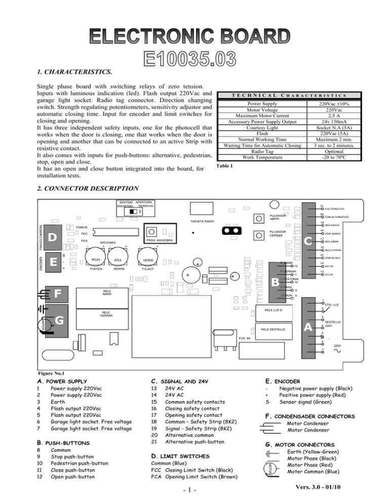
1. CHARACTERISTICS. Single phase board with switching relays of zero tension. Inputs with luminous indication (led). Flash output 220Vac and TECHNICAL CHARACTERISTICS garage light socket. Radio tag connector. Direction changing Power Supply 220Vac ±10% switch. Strength regulating potentiometers, sensitivity adjustor and Motor Voltage 220Vac automatic closing time. Input for encoder and limit switches for Maximum Motor Current 2,5 A closing and opening. Accessory Power Supply Output 24v 150mA Courtesy Light Socket N.A (5A) It has three independent safety inputs, one for the photocell that Flash 220Vac (5A) works when the door is closing, one that works when the door is Normal Working Time Maximum 2 min. opening and another that can be connected to an active Strip with Waiting Time for Automatic Closing 3 sec. to 2 minutes. resistive contact. Radio Tag Optional It also comes with inputs for push-buttons: alternative, pedestrian, Work Temperature -20 to 70ºC stop, open and close. Table 1 It has an open and close button integrated into the board, for installation tests. 2. CONNECTOR DESCRIPTION Figure No.1 A. POWER SUPPLY C. SIGNAL AND 24V E. ENCODER 1 2 3 4 5 6 7 13 14 15 16 17 18 19 20 21 + S Power supply 220Vac Power supply 220Vac Earth Flash output 220Vac Flash output 220Vac Garage light socket. Free voltage Garage light socket. Free voltage B. PUSH-BUTTONS 8 9 10 11 12 Common Stop push-button Pedestrian push-button Close push-button Open push-button 24V AC 24V AC Common safety contacts Closing safety contact Opening safety contact Common – Safety Strip (8K2) Signal - Safety Strip (8K2) Alternative common Alternative push-button D. LIMIT SWITCHES Common (Blue) FCC Closing Limit Switch (Black) FCA Opening Limit Switch (Brown) -1- Negative power supply (Black) Positive power supply (Red) Sensor signal (Green) F. CONDENSADER CONNECTORS Motor Condenser Motor Condenser G. MOTOR CONNECTORS Earth (Yellow-Green) Motor Phase (Black) Motor Phase (Red) Motor Common (Blue) Vers. 3.0 - 01/10 3. START -UP. OFF ON Figure 2 ATTENTION: Before making any adjustments or alterations to the equipment, always ensure it is disconnected from the power supply. Always connect the earth cable, to ensure better protection. 1. Put the cables through the cable ducts and connect the accessories to the power supply. Separate the power supply cables (220Vac) from those used for control and safety devices (24Vac signal) 2. Position the door to the centre of its trajectory and block the motor. The equipment includes a safety system that deactivates the working of the door when the unblocking device is activated, the lever must be closed and the key in vertical position. 3. Turn the switch (No.1) ON. 4. If one wants to use radio emitters, connect the receiver tag (No.2) 5. Memorise the emitters according to model. If the tag has two channels, the second channel can be used as a pedestrian opening. (see point 3.1) 6. Position the micro-switch (No.3) depending on the opening direction (left-right). 7. Choose the positions for the micro-switches (No.4) according to needs (Table 2). 8. Using the open and close push-buttons (No.6) integrated into the board, confirm the correct positioning of the limit switches, that the door opens and closes as appears on push-buttons. During the programming, the pushbuttons work as “hombre presente”. 9. Press the programming button (No.5) for 1, 5 seconds, the red led turns on and remains on during the programming. The programming mode deactivates after 15 seconds of inactivity, exit can be forced by pressing the same button again. 10. Follow the next steps depending on the type of programming selected. (Table 2 micro-switches No.1). AUTOMATIC PROGRAMMING The automatic programming can be started from any position of the door, except completely open. Press the emitter or the alternative push-button. If the door is not closed, a closing manoeuvre will commence, followed by two complete cycles (open-close-open-close). Once the efforts and distances have been memorised, the led will turn off and the learning process will have concluded. MANUAL PROGRAMMING The manual programming must start with the closing limit switch activated. Press the emitter or alternative push-button and the door will start opening. During the trajectory, activate the alternative push-button or remote control at the point where we want the smooth stop to begin. The opening learning process will finalize when reaching the opening limit switch. Repeat the same operation for close learning process. When it has finished, the led will turn off and the learning process will have concluded. 11. Adjust the strength and sensitivity (No.7) (see points 4.2.1 and 4.2.2)in compliance to current law EU-EN 12453 -2- 3.1. PARTIAL OPENING PROGRAMMING (PEDESTRIAN) This feature can be programmed and used by means of a two channel receiver or by the pedestrian input push-button (connector No.10). To memorize the second channel, see receiver and emitter instructions. The predefined opening, from the manufacturer, is of 1 metre. If one wishes to modify the distance, follow these steps: To start the programming process, the door must be closed and the limit switch activated. Press the programming pushbutton (No.5) for 1, 5 seconds and the led will light up. Activate the emitter channel or the push-button for pedestrian opening and the door will start to open. When it has reached the selected distance, press the emitter to stop the door and establish the partial opening. 4. CONFIGURATION AND ADJUSTMENTS: 4.1. MICRO-SWITCH FUNCTIONS. Table 2 Nº FUNCTION 1 Type of learning 2 Automatic closing 3 Receiver function 4 Push-button input 5 Light socket 6 Photocell closure OPTION OBSERVATION ON: Manual OFF: Automatic ON: Yes OFF: NO ON: open-stop-close-open OFF:open-stop-close-stop-open ON: Funcioning by impulse OFF: "Hombre presente" ON: Timer OFF: Impulse ON: Activated The distance of the smooth stop can be selected Smooth stop distance predetermined at 20cm Timer with green potentiometer Alternative push-button sequence (No.7 on OFF) Alternative push-button sequence (No.7 on OFF) the button must be pressed Coutesy light for 3 minutes Garage light socket, 3 seconds Closing in 5 sec, after photocell is liberated. Automatic closing must be ON. OFF: Deactivated 7 With door open and keeping the push-button pressed for 3 sec, closing will be forced. OFF: Alternative push-button The sequence is open-stop-close-stop-open ON: Maximum OFF: Smotth For heavy doors. For light weight doors. To allow the strip to be in contact with the frame. The strip is inhibited for the last 4cm. Receiver function 8 Start and brake 9 Inhibition strip 10 ON: Alternative push-button only opens Anti-crushing ON: Activated* OFF: No ON: Delayed anti-crushing OFF: Sensitivity activated For doors with friction. Imediate reaction when an obstacle is present *With function 10 ON, the automatism must be used in “hombre presente” mode (function 4 ON) to comply with current law EUEN 12453. 4.2. REGULATING THE POTENTIOMETERS: Less More 4.2.1 Regulating strength and sensitivity in normal trajectory (red) When the potentiometer is turned clockwise, the strength of the motor increases and the sensitivity in presence of an obstacle diminishes during a trajectory at normal speed. When turning the potentiometer anti-clockwise, the strength of the motor diminishes and the sensitivity in presence of an obstacle increases during a trajectory at normal speed. 4.2.2 Regulating the sensitivity and speed in smooth stop (blue) When turning the potentiometer clockwise, the smooth stop and sensitivity increases in presence of an obstacle. When turning the potentiometer anti-clockwise, the smooth stop and sensitivity diminishes in presence of an obstacle. 4.2.3 Automatic lowering time (green) When turning the potentiometer clockwise, the automatic lowering increases (maximum: 120sec). When turning the potentiometer anti-clockwise, the automatic lowering time diminishes (minimum: 3sec) -3- 5. ELECTRICAL CONNECTIONS: 5.1 External manoeuvre At the alternative push-button input (Diagram. No.1) the door goes through sequence open-stop-close-stop-open for each impulse it receives, either by means of a push-button or by an external radio control receiver. There is also an input for push-button open, close, pedestrian and stop. (Diagram No.2) Diagram 1 5.2 Garage light socket Diagram 2 The garage light output socket is a voltage free socket, working when the closing manoeuvre starts and can be used as: Courtesy light (Diagram No.3) micro-switches 5 in ON position Garage light (Diagram No.4) micro-switches 5 in OFF position . Diagram 3 Diagram 4 5.3 Flash output By defect the output is of 220Vac fixed and works during the closing or opening manoeuvre. (Diagram No.5) To activate the flash, the switch (No.1 Fig.2) must be OFF, press the programming button (No.5 Fig.2) and maintain it pressed for 3 seconds alter positioning the switch (No.1 Fig.2) ON. To deactivate this option, repeat the same operation Detailed functioning of the flash: • Door during opening and closing, flash in both directions. Faster during closure. • Door open, light on without flashing. • Automatic closing activated 5 second prior notice before closing. Diagram 5 5.3 Safety strip The connection varies depending on whether the strip contact is N.C (Diagram No.6) or N.A (Diagram No.7). If it is activated during the opening manoeuvre, it stops and reverses the manoeuvre during 2 seconds. If it is activated during the closing manoeuvre, it stops and reverses the complete manoeuvre. Diagram 6 Diagram 7 5.4 Photocell The photocell, with its contact normally closed is connected between the connectors 15-16 (close) and 15-17 (open). If the opening photocell is activated during an opening manoeuvre, it stops and reverses the manoeuvre during 2 seconds. If the closing photocell is activated during a closing manoeuvre, it stops and reverses the complete manoeuvre. Example depending on the type of photocell, closing connection (Diagram No.8 and No.9) Diagram 9 Diagram 8 -4


