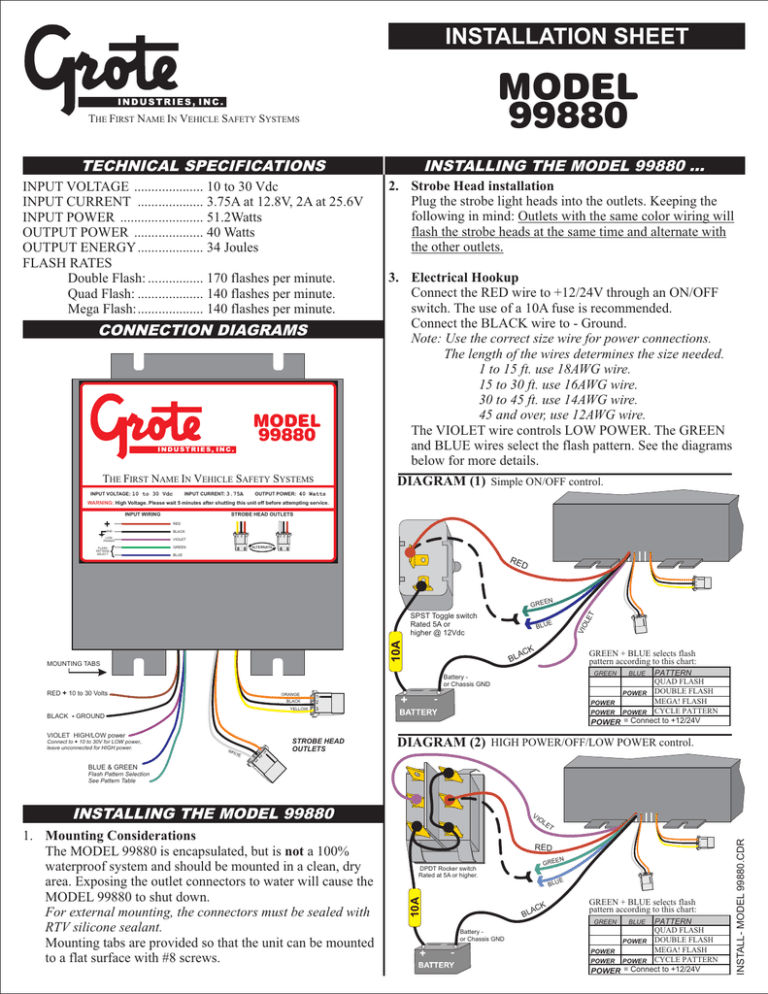
Wiring Diagram (99880)
advertisement

INSTALLATION SHEET MODEL 99880 THE FIRST NAME IN VEHICLE SAFETY SYSTEMS TECHNICAL SPECIFICATIONS INPUT VOLTAGE .................... 10 to 30 Vdc INPUT CURRENT ................... 3.75A at 12.8V, 2A at 25.6V INPUT POWER ........................ 51.2Watts OUTPUT POWER .................... 40 Watts OUTPUT ENERGY................... 34 Joules FLASH RATES Double Flash: ................ 170 flashes per minute. Quad Flash: ................... 140 flashes per minute. Mega Flash:................... 140 flashes per minute. CONNECTION DIAGRAMS MODEL 99880 THE FIRST NAME IN VEHICLE SAFETY SYSTEMS INPUT VOLTAGE: 10 to 30 Vdc INPUT CURRENT: 3.75A INSTALLING THE MODEL 99880 … 2. Strobe Head installation Plug the strobe light heads into the outlets. Keeping the following in mind: Outlets with the same color wiring will flash the strobe heads at the same time and alternate with the other outlets. 3. Electrical Hookup Connect the RED wire to +12/24V through an ON/OFF switch. The use of a 10A fuse is recommended. Connect the BLACK wire to - Ground. Note: Use the correct size wire for power connections. The length of the wires determines the size needed. 1 to 15 ft. use 18AWG wire. 15 to 30 ft. use 16AWG wire. 30 to 45 ft. use 14AWG wire. 45 and over, use 12AWG wire. The VIOLET wire controls LOW POWER. The GREEN and BLUE wires select the flash pattern. See the diagrams below for more details. DIAGRAM (1) Simple ON/OFF control. OUTPUT POWER: 40 Watts WARNING: High Voltage. Please wait 5 minutes after shutting this unit off before attempting service. INPUT WIRING STROBE HEAD OUTLETS RED GND BLACK LOW POWER VIOLET FLASH PATTERN SELECT ALTERNATE GREEN BLUE RE D 1 2 3 EN 10A BL AC VIO E K GREEN + BLUE selects flash pattern according to this chart: PATTERN QUAD FLASH POWER DOUBLE FLASH MEGA! FLASH POWER POWER POWER CYCLE PATTERN POWER = Connect to +12/24V GREEN Battery or Chassis GND RED + 10 to 30 Volts ORANGE BLACK YELLOW BLACK - GROUND VIOLET HIGH/LOW power Connect to + 10 to 30V for LOW power,. leave unconnected for HIGH power. WH ITE 3 2 1 1 2 3 STROBE HEAD OUTLETS 1 2 3 MOUNTING TABS BLU LE T GRE SPST Toggle switch Rated 5A or higher @ 12Vdc BLUE DIAGRAM (2) HIGH POWER/OFF/LOW POWER control. BLUE & GREEN Flash Pattern Selection See Pattern Table INSTALLING THE MODEL 99880 OL 1 2 3 RED EN GRE DPDT Rocker switch Rated at 5A or higher. 10A BLU BL AC K E GREEN + BLUE selects flash pattern according to this chart: PATTERN QUAD FLASH DOUBLE FLASH POWER MEGA! FLASH POWER POWER POWER CYCLE PATTERN POWER = Connect to +12/24V GREEN Battery or Chassis GND BLUE INSTALL- MODEL 99880.CDR ET 1 2 3 1. Mounting Considerations The MODEL 99880 is encapsulated, but is not a 100% waterproof system and should be mounted in a clean, dry area. Exposing the outlet connectors to water will cause the MODEL 99880 to shut down. For external mounting, the connectors must be sealed with RTV silicone sealant. Mounting tabs are provided so that the unit can be mounted to a flat surface with #8 screws. VI

