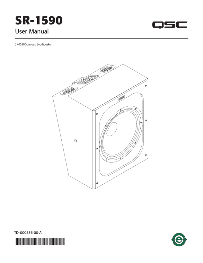
SR-1590
User Manual
SR-1590 Surround Loudspeaker
TD-000536-00-A
*TD-000536-00*
EXPLANATION OF SYMBOLS
The term “WARNING!” indicates instructions regarding personal safety. If the instructions are not followed the result may be bodily injury or death.
The term “CAUTION!” indicates instructions regarding possible damage to physical equipment. If these instructions are not followed, it may result in
damage to the equipment that may not be covered under the warranty.
The term “IMPORTANT!” indicates instructions or information that are vital to the successful completion of the procedure.
The term "NOTE" is used to indicate additional useful information.
The intent of the exclamation point within an equilateral triangle is to alert the user to the presence of important safety, and operating
and maintenance instructions in this manual.
IMPORTANT SAFETY INSTRUCTIONS
1. Keep these instructions.
2. Heed all warnings.
3. Follow all instructions.
4. Do not use this apparatus near water.
5. Clean only with a dry cloth.
6. Do not block any ventilation opening. Install in accordance with the manufacturer's instructions.
7. Do not install near any heat sources such as radiators, heat registers, stoves, or other apparatus (including amplifiers) that produce heat.
8. Only use attachments/accessories specified by the manufacturer.
9. Refer all servicing to qualified service personnel. Servicing is required when the apparatus has been damaged in any way, such as liquid has
been spilled or objects have fallen into the apparatus, the apparatus has been exposed to rain or moisture, does not operate normally, or has
been dropped.
10.Adhere to all applicable, local codes.
11.Always keep sound pressure levels in the listening area below levels that can damage human hearing.
Warranty
For a copy of the QSC Limited Warranty, visit the QSC website at www.qsc.com
TD-000536-00-A
2
Introduction
The SR-1590 is a high-power, compact cinema surround loudspeaker that addresses the requirements of the new immersive sound formats.
The SR-1590 is designed for safe and secure overhead mounting:
• Pre-installed hardware allows fast single-installer wall mounting with optional wall brackets supporting down-angles of 0° or 8°.
• A traditional U-bracket or yoke (YM-500) is also available.
• The rear panel of the cabinet has ten M6 threaded insert mounting points that accommodate the standard bolt pattern for most third-party bracket
manufacturers.
• Four of the mounting points are centered on the cabinet’s rear panel allowing the use of a multiple angle aiming bracket.
SR-1590 Package Contents
1 SR-1590 Loudspeaker
1 M6 Eyebolt
1 User Guide
Warranty TD-000453
Installing the SR-1590
WARNING!: Read and follow these instructions carefully. If the loudspeakers are not suspended properly, they could fall,
causing personal injury and damage to the equipment.
Rules for Suspension
1. Consult a Professional Mechanical or Structural Engineer, licensed in the jurisdiction of the sound system installation, to review, verify, and approve
all attachments to the building or structure.
2. Employ the services of a Professional Rigger for hoisting, positioning, and attaching the equipment to the supporting structure.
3. Correct use of all suspension hardware and components is imperative in sound system suspension and deployment.
4. Always calculate suspended loads before lifting to make sure suspension components and hardware are used within their respective load limits.
5. Consult local codes and regulations to fully understand the requirements for suspended loads in the venue in which you will suspend the
equipment.
6. Use only the recommended brackets with the M8 and M6 installation points.
7. Be absolutely certain of the integrity of any structural member intended to support suspended loads. Hidden structural members can have hidden
structural weakness.
8. Never assume anything! Owner or third-party supplied suspension attachment points may not be adequate for suspending the loads.
Safety Cable
1
WARNING!: For any overhead installation, you must use safety cables (not included)
attached to the supporting structure and the loudspeaker enclosure.
2
Refer to — Figure 1
1. Install the included M6 threaded shoulder eyebolt (2) into one of the unused M6 threaded inserts on
the back of the enclosure.
2. Attach one end of the safety cable (1) to the support structure, and the other end to the eyebolt on
the loudspeaker enclosure.
— Figure 1 —
IMPORTANT: All 12 threaded inserts must have fastening hardware (screws or eyebolt)
securely installed. The insert holes are open into the enclosure. If a hole is left open it
creates an air leak and the performance of the loudspeaker will be compromised. If the hardware is not securely installed it may rattle
and/or fall out.
TD-000536-00-A
3
WARNING!: Be sure to read the "Rules for Suspension" on page 3 before installing the loudspeaker.
Wall Mounting
Refer to — Figure 2.
Refer to TD-000381 "Surround Mounting Brackets" user manual (delivered with the mounting
brackets), for mounting instructions.
1
The SR-1590 comes with a pre-attached bracket (1) for use with QSC's QM-SW or QM-BW wall
bracket (order separately).
Yoke Mounting
2
Refer to — Figure 3 and — Figure 4.
Refer to TD-000376 "Yoke Mount Bracket User Manual" (delivered with the mounting yoke), for
mounting instructions.
WARNING!: Do not use the slot in the yoke when mounting from the ceiling;
use one of the two holes on either side of the slot.
— Figure 2 —
You can use the YM-500 Yoke Bracket for mounting the loudspeaker on the wall, or on the ceiling.
M6 Eye Bolt for
Safety Cable
— Figure 4 —
— Figure 3 —
TD-000536-00-A
4
Third-party Brackets
Refer to — Figure 5.
WARNING!: Be sure to use a
safety cable as described in
"Safety Cable" on page 3.
The back panel of the enclosure has ten
mounting points, that conform to the standard
2.75 x 5.0 inch hole mount pattern. These ten
mounting points allow you to use a standard
4-hole bracket in one of four locations. If you use
a multi-mount wall bracket you can get more
horizontal pan by using the outer set of threaded
inserts toward the direction of the panning.
— Figure 5 —
1. Use a Phillips screwdriver to remove the pre-installed bracket, part (1), on — Figure 2.
2. Install your selected mounting bracket according to the manufacturer's instructions. Be sure to replace screws into any unused holes. (— Figure 5)
Loudspeaker Connections
The SR-1590 has a 4-position screw-type barrier strip, which accepts up to 10-gauge (10 AWG) bare wire or spade lugs. Be sure to maintain consistent
polarity from the amplifier to the loudspeaker’s input terminals.
You can wire each loudspeaker individually ("home-run") a single amplifier channel or, you can wire the loudspeakers in parallel (daisy-chained).
However, since the SR-1590 is a 4 Ω loudspeaker, we recommend wiring each loudspeaker individually to a single amplifier channel.
IMPORTANT: Be sure to check the amplifier’s specifications for load requirements when you wire loudspeakers in parallel.
Make sure you maintain the proper polarity from the amplifier to each of the loudspeakers you connect.
Amplifier
+
INPUT
+
OUTPUT
+
INPUT
+
OUTPUT
— Figure 6 —
1. Connect the wires from the amplifier – and + to the – and + INPUTS of the loudspeaker's barrier-strip connector.
2. Make sure the wires are secured to the connector.
3. Secure the wires with the proper strain relief as needed.
4. If you are connecting loudspeakers in parallel (daisy-chain), connect the wires to the – and + to the – and + OUTPUTS of the loudspeaker's barrier
strip connector, and the other ends to the – and + to the – and + INPUTS of the next loudspeaker's barrier strip connector.
TD-000536-00-A
5
SR-1590 Dimensions
127 mm
5 in
396 mm
15.6 in.
127 mm
5.0 in
70 mm 70 mm 70 mm
2.75 in 2.75 in 2.75 in
514 mm
20.2 in.
392 mm
15.0 in
350 mm
14.0 in
600 mm
24.0 in.
552 mm
22.0 in
500 mm
20.0 in
207 mm
8.0 in
TD-000536-00-A
6
Specifications
System Details
SR-1590
Description
15" (381 mm) 4 ohms 2-way coaxial loudspeaker
Frequency range (-10 dB) 1
50 Hz – 20 kHz
Rated impedance
4 Ω nominal
Rated noise power 2
500 W
Sensitivity
98 dB
3
Maximum continuous SPL 4
125 dB
Maximum peak SPL
4
131 dB
Maximum recommended amplifier power
1000 W
Rated coverage angle (-6 dB)
90° conical (averaged from 1 kHz to 8 kHz)
Directivity factor
7.6
Directivity index (dB)
5
8.8
LF transducer
15" (381 mm) weather resistant paper cone woofer, 3” (76 mm) voice-coil
HF transducer
1.4 in (36 mm) exit, 3 in (76 mm) voice coil compression driver
Input connector type
4-position barrier strip, accepts up to #10 AWG stranded wire
Enclosure Details
Material
15 mm Baltic Birch Plywood
Finish
Non-reflective black vinyl
Grille
Black cloth
Wall Mounting
Baffle is 15° downward for wall-mounting install using QSC QM-SW or 23° using QSC QM-BW
Ceiling Mounting
Attachment points for ceiling install using third-party mounting brackets.
Safety
Tethering point for safety cable
Net weight
19.5 lb (43 kg)
Shipping weight
56.8 lb (25.82 kg)
Product dimensions (H x W x D)
24" x 20" x 15.4" (600 mm x 500 mm x 392 mm)
Shipping dimensions (H x W x D)
27.8" x 22" x 18.38" (705 mm x 589 mm x 467 mm)
Optional Accessories
QM-SW (side wall mount), QM-BW (back wall mount), YM-500 (yoke mount)
1 2 3 4 5 Processed, free-field, -10 dB from on-axis sensitivity
AES2-1984 noise signal for 2 Hours
On-Axis, free-field sensitivity, 2.0 V, 1 m
Calculated from rated noise voltage and sensitivity
Average (500Hz - 8kHz)
As part of QSC’s ongoing commitment to product development, specifications are subject to change without notice.
TD-000536-00-A
7
Mailing Address:
QSC, LLC
1675 MacArthur Boulevard
Costa Mesa, CA 92626-1468 USA
Telephone Numbers:
Main Number: (714) 754-6175
Sales & Marketing: (714) 957-7100 or toll free (USA only) (800) 854-4079
Customer Service: (714) 957-7150 or toll free (USA only) (800) 772-2834
Facsimile Numbers:
Sales & Marketing FAX: (714) 754-6174
Customer Service FAX: (714) 754-6173
World Wide Web:
www.qsc.com
E-mail:
info@qsc.com
service@qsc.com
© 2016 QSC, LLC. All rights reserved. QSC and the QSC logo are registered trademarks of QSC, LLC in the U.S. Patent and Trademark office and other countries. All other
trademarks are the property of their respective owners.
http://patents.qsc.com.


