Congestion relief
advertisement
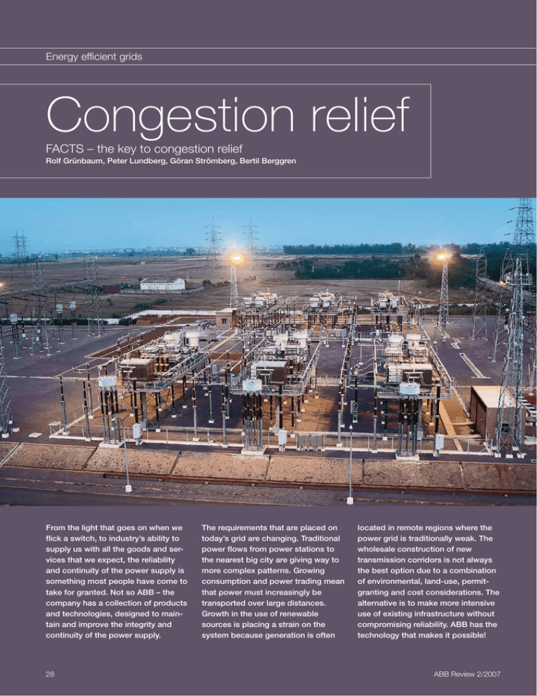
Energy efficient grids Congestion relief FACTS – the key to congestion relief Rolf Grünbaum, Peter Lundberg, Göran Strömberg, Bertil Berggren From the light that goes on when we flick a switch, to industry’s ability to supply us with all the goods and services that we expect, the reliability and continuity of the power supply is something most people have come to take for granted. Not so ABB – the company has a collection of products and technologies, designed to maintain and improve the integrity and continuity of the power supply. 28 The requirements that are placed on today’s grid are changing. Traditional power flows from power stations to the nearest big city are giving way to more complex patterns. Growing consumption and power trading mean that power must increasingly be transported over large distances. Growth in the use of renewable sources is placing a strain on the system because generation is often located in remote regions where the power grid is traditionally weak. The wholesale construction of new transmission corridors is not always the best option due to a combination of environmental, land-use, permitgranting and cost considerations. The alternative is to make more intensive use of existing infrastructure without compromising reliability. ABB has the technology that makes it possible! ABB Review 2/2007 Congestion relief Energy efficient grids T he concept of transmission congestion implies, by definition, that there are limitations to how much power can be transferred across a transmission interface, and further that there is an incentive to actually desire to transfer more power. This incentive is often based on differences in power production costs on either side of the interface – a factor that has become more transparent through recent deregulation measures. In other words, there are consumers on at least one side of the interface who could benefit from being able to purchase power produced on the other side. But before such trading can become viable, the infrastructure must be able to support it. The traditional approach to remedying congestion lies in reinforcing the system with additional transmission capacity (eg adding overhead lines). Although still feasible, this approach is becoming more and more complex and it is often challenged by the public. It is becoming increasingly difficult and time-consuming to obtain the permits to building new transmission corridors, or even expand existing ones. An alternative that can postpone or altogether avoid the need for such investments lies in improving the utilization of existing infrastructure by permitting more flexibility and controllability. This can be done through the installation of controllable devices in the transmission system, such as FACTS (Flexible AC Transmission System) devices, possibly supplemented with advanced information gathering systems. Although, in general terms, the concept is commonly accepted, the application of these measures involves a number of challenges requiring attention. FACTS solutions for congestion relief Typically, different solutions can be envisaged – the solution selected depends on the nature of the physical constraint. However, the operational environment in which these solutions are applied is common to all, and the associated control strategies can to some extent be generalized. ABB Review 2/2007 In a general setting, the philosophy behind corrective control as applied to FACTS devices for mitigation is similar to that shown in 1 . The traditional approach to remedying congestion lies in reinforcing the system with additional transmission capacity (eg adding overhead lines). Although still feasible, this approach is becoming more and more complex and it is often challenged by the public. Dissection of a fault handling scenario During more than 99 percent of operating time, the focus of the control system is on loss minimization and on loop flow control relative to neighboring networks. Following a disturbance, the control objective instantly changes to handling the physical limitations of the network. Following the clearance of a network fault, transient phenomena must be attended to. These phenomena, which include first swing stability; power oscillation damping (POD); voltage stability/recovery and frequency control, require an adequate speed of control if mitigation is to be succesful. After 10 to 20 seconds, when the transient period is over and the post-dis1 turbance period starts, slower phenomena may require attention. The control objective switches to address these phenomena, which can include thermal limitations, voltage support (to avoid slow voltage collapse) and frequency support. After 20-30 minutes the operator should have assessed the situation and taken proper actions to secure a system state that again allows equipment failures without risking such drastic consequences as blackouts. Corrective control applied to FACTS devices is thus a general control strategy that provides means for efficient operation in the pre-disturbance period while still maintaining security in a robust way. Or phrased differently, it is a way to provide the operator with as much time as possible in the event of severe disturbances. The FACTS devices available provide different means of fulfilling the control objectives indicated in 1 . FACTS solutions are usually subdivided into shunt compensation and series compensation. SVC and STATCOM Static VAr Compensators (SVC) and Static Compensators (STATCOM) are shunt-connected at critical locations in the transmission grid. Both device types use power electronics to dynamically control the generation or consumption of reactive power. This reactive power is exchanged with the grid to control the system voltage. In addition to providing dynamic voltage Corrective control objectives – setting the right priorities is the key to mastering the disturbance and preventing blackouts. Fault-on plus 20 – 30 minutes Fault-on Predisturbance Transient Postdisturbance Loss minimization First swing stability Thermal limits Loop flow control POD Voltage support Voltage stability/recovery Frrequency support Operator action Time Frequency control 29 Congestion relief Energy efficient grids support in both the short and long time perspective, these devices are capable of providing power oscillation damping in the transient period [1]. 2 STATCOM (static compensator) equipment performs dynamic voltage control by producing or consuming reactive power. The main features of the SVC, the classical FACTS device, are described in [2]. STATCOM 2 is built on the power electronic concept of voltage source conversion. The ABB version, SVC Light®, uses IGBTs. This type of converter enables high performance features such as: Robust voltage support under severe disturbances Balancing of asymmetrical and rapidly fluctuating loads Power oscillation damping Active filtering of harmonic currents SVC Light is described in [3] and [4] for a number of applications where high performance is needed. During more than 99 percent of operating time, the focus of the control system is on loss minimization and on loop flow control relative to neighboring networks. STATCOM with Energy Storage An optional enhancement of SVC Light is an energy storage feature consisting of series-connected batteries 3 [5]. The size of the energy storage depends on the optimization of performance versus cost. The discharge time, ie operating time at full active power, is in the order of 15 to 30 minutes in the base case. Energy storage enables the STATCOM to also deliver and consume active power during a period of time. The voltage source converter (VSC) uses series-connected IGBTs to deliver high performance and high power. The battery charge must be controlled throughout the complete load cycle. A typical application example is in conjunction with a renewable energy source such as a wind farm that has a strongly fluctuating production. The load balancing function with energy 30 storage delivers active power at a scheduled power level and reactive consumption/production within operational limits, according to the setpoint from the dispatch center. 3 Dynamic energy storage with SVC Light Pload Qload generator line load Thus, the combination of a renewable energy source and a STATCOM with energy storage can permit this otherwise intermittent source of energy to be used in the same way as a conventional production source1). Other benefits for the power system are the use of such devices in emergency operations for black starts or reconstruction of the network using the available frequency and voltage controls. With a STATCOM capable of modulating both active and reactive power output, power oscillation damping can be greatly improved. This permits higher power transfer levels and so relieves congestion. In principle, energy storage solutions are able to change the time at which a given power-flow across a congested interface occurs (if the storage solution is installed on the receiving side of the transmission corridor). Energy is stored in absence of congestion, and discharged when congestion re- Pinj energy storage Qinj SVC Light 4 Schematic configuration of TCSC (thyristor controlled series compensation) – TCSC permits variable series compensation L iV iL C + UC 5 TCSC equipment used for power oscillation damping Footnote 1) Intermittent sources of energy such as wind turbines normally require a spinning reserve of conventional power plants to back them up should availability drop. A measure such as this which permits energy to be buffered allows such reserves to be dispensed with or deployed otherwise. ABB Review 2/2007 Congestion relief Energy efficient grids turns. On the scale of a power grid, the energy storage capability that would be required would be too large to be feasible. However, for individual consumers, it may be an economically viable solution – in particular when there are power quality problems to be addressed. A further application of STATCOM with energy storage would be as a frequency-controlled active disturbance reserve, in particular if it is installed on the receiving side of a frequently congested interface. Such an installation could additionally reduce the gap between transmission capacity and trading demands. Thyristor Controlled Series Compensation (TCSC) Other FACTS devices also have the ability to affect active power flows, even if they do not have energy storage capabilities. In particular, series devices can be used for this purpose. TCSC 4 5 is often used at bottlenecks in which the power transfer limit is determined by poor damping of power oscillations. The technology has in particular been proven effective for situations where weaknesses in the transmission grid tend to split the system into two separate large groups of generators. The solution typically involves fixed series compensation combined with a smaller thyristor-controlled section. The latter is controlled to actively dampen the power oscillations. This more precise matching of damping to line conditions permits a larger power transfer [6]. Lately, the ability to additionally perform active power flow control in the steady state has received increasing interest, in particular in the aftermath of recent blackouts. Even though a high boost TCSC has the capability to perform power flow control, it is often a better solution to subdivide the capacitor branch into a chain of series connected thyristor-switched capacitor steps. The outcome is a thyristor-switched series capacitor (TSSC). This can be seen in the right-hand part of 6 . For a power flow control application, it is natural to compare the TSSC with a PST (Phase Shifting Transformer). Whereas the PST is adequate for handling thermal limitations, it is too slow to mitigate phenomena occurring in the transient period. Furthermore, it has a deteriorating effect on the voltage profile, both in the short and long time perspective, and reduces angular stability in some cases. The TSSC on the other hand is fast enough to act decisively to mitigate the transient phenomena, and can support voltages both in the perspective of short and long timeframes. However, whereas the PST can both increase and decrease the power flow on the path in which it is installed, the TSSC can only increase the flow. Furthermore, as a rule of thumb, the reactance of a TSSC should be limited to roughly 60 percent of the reactance between the two substations on each side of the TSSC. Thus, if the required 6 The essential principle of TCSC is that the forward-biased thyristor is fired just before the zero voltage crossing at the capacitor. This injects additional current into the capacitor and increases the apparent reactance, typically up to a factor of three times the original reactance. This variation, which is referred to as boosting, helps mitigate the power oscillations. Contrary to the fixed series capacitor, the TCSC appears inductive in the frequency range below its fundamental frequency, thus effectively eliminating concerns for SSR (sub-synchronous resonance) for the TCSC part in relation to nearby turbine generators. ABB Review 2/2007 power flow control capability is large (depending on the network topology) the TSSC solution may not be adequate. Dynaflow For the purpose of relieving congestion in areas where combinations of control objectives are of concern, ABB is developing a power flow control concept called Dynaflow. It consists of a PST in series with a multi-step TSSC with coordinated control 6 . Clear and transparent mechanisms for sharing responsibilities between system operators are advantageous for successful implementation of corrective control actions. The total power flow control capability is divided between the PST and the TSSC, resulting in a smaller PST and TSSC. Dynaflow combines the positive qualities of both devices. It is thus capable of performing loss minimization and/or loop flow control in the predisturbance period, improving first swing stability, power oscillation damping and/or voltage performance in the transient period and supporting voltages and/or thermal limitations in the post-disturbance period. The control system and the necessary input signals for control are customized for the particular bottleneck to which it is Schematic configuration of Dynaflow – Dynaflow consists of a phase shifting transformer in series with a multi-step TSSC with coordinated control. Thyristor Control Phase-shifting Transformer C1 TSSC1 TapChanger Control Master Control C2 TSSC2 C3 TSSC3 System Inputs 31 Congestion relief Energy efficient grids applied. The introduction of high performance communication and measurement systems provides a basis for additional performance. A typical application of Dynaflow would be in relation to city infeed. Highly populated cities are often characterized by having large consumption of active and reactive power while the generation sources are remotely located. This frequently has the consequence that the transmission lines feeding the city are heavily loaded and that dynamic reactive power resources are lacking. A typical critical disturbance would be a line fault followed by a permanent disconnection of the faulted line. Assuming that the power flow would be unevenly distributed on the remaining transmission paths, and Dynaflow is installed on the path designed to pick up more load in order to avoid overloading the parallel paths, the sequence of control objectives could be as follows: In the pre-disturbance period, focus is on minimizing active system losses. A set-point would typically be obtained from a control center possibly based on an optimal power flow calculation. Immediately following the fault, all capacitive steps are switched in for the purpose of supporting a voltage recovery. This is particularly important for cities with a considerable proportion of electrical motor loads (eg in the form of air conditioning units). Without voltage support these units would have a tendency to stall and so become a significant drain on reactive power; this in turn can result in local voltage collapse and cascading outages. Once voltages have recovered, the control objective would shift to thermal limits. By combining the capability of the PST and the TSSC, power flow is controlled to avoid overload in the path in which the Dynaflow is installed or in parallel paths. Furthermore, if the initiating events are so severe that the overload cannot be completely removed, power flows can be distributed to give the operator as much time as possible to take remedial actions. This would typically imply that the 32 overload is evenly distributed between the parallel paths. WAMS and WACS A corrective control scheme with the capability to perform dynamic power flow control taking also parallel paths into consideration generally requires that remote measurements are available. Recent advances in the fields of Wide Area Measurements Systems (WAMS) and communications, together with FACTS, open up new possibilities for such Wide Area Control Systems (WACS). Situations with several dynamic power flow control devices installed on parallel paths would in addition require a coordination of the control efforts. For the purpose of relieving congestion in areas where combinations of control objectives are of concern, ABB is developing a power flow control concept called Dynaflow. as well as Dynaflow as three viable options for congestion relief. The application of corrective control will in many cases benefit from the application of advanced information and control systems customized for the particular bottleneck. It is important that operation planning is provided with efficient security assessment tools such that full advantage can be taken of the installations. This is in particular important when handling congestions on the interface between different systems. Rolf Grünbaum Peter Lundberg Göran Strömberg ABB Power Technologies Västerås, Sweden rolf.grunbaum@se.abb.com peter.lundberg@se.abb.com goran.stromberg@se.abb.com Related issues There are obviously limits to what can be accomplished with controllable devices. These limits will determine the new level of power transferred across a transmission interface. From an operational planning point of view it will become important to have efficient security assessment tools, permitting full advantage to be taken of the installed devices. Bertil Berggren ABB Corporate Research Västerås, Sweden bertil.berggren@se.abb.com References [1] Mathur, R. M, Varma, R. K, Thyristor-based FACTS Controllers for Electrical Transmission Systems, IEEE Press, 2002. ISBN 0-471-20643-1 [2] Hingorani, N.G., Gyugyi, L, Understanding FACTS: Concepts and Technology of Flexible AC For historical reasons, bottlenecks are often found on the interface between different grids. Clear and transparent mechanisms for sharing responsibilities between system operators are typically advantageous for successful implementation of corrective control actions. Transmission Systems, IEEE Press, 1999. ISBN 0-7803-3455-8 [3] Larsson, T, Ratering-Schnitzler, B, “SVC-Light: A utility’s aid to restructuring its grid,” IEEE PES Winter Meeting, Singapore, January 2000. [4] Grünbaum, R, et al, “FACTS: Powerful means for dynamic load balancing and voltage support of AC traction feeders,” IEEE Power Tech, Porto, Portugal, September 10–13, 2001. [5] Svensson, J, Jones, P, Halvarsson, P, ”Im- Conclusions proved Power System Stability and Reliability FACTS include a portfolio with controllable devices that can relieve congestions and improve the efficiency of the existing network. The exact type to be selected is determined by the nature of the bottleneck. There are often different options. This article presents STATCOM with Energy Storage, TCSC, using Innovative Energy Storage Technologies,” In Proc. IEE ACDC 2006, London, U.K., pp. 220–224. [6] Gama, C, Angquist, L, Ingestrom, G, Noroozian, M, ”Commissioning and operative experience of TCSC for damping power oscillations in the Brazilian North-South Interconnection,” In Proc. CIGRE Session 2000, Paris, France, 2000, pp. 14–104. ABB Review 2/2007
