Development of pulsed power generators for
advertisement

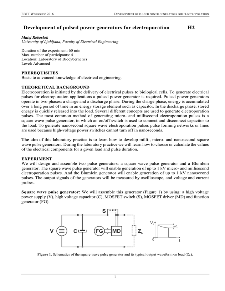
EBTT WORKSHOP 2016 DEVELOPMENT OF PULSED POWER GENERATORS FOR ELECTROPORATION Development of pulsed power generators for electroporation H2 Matej Reberšek University of Ljubljana, Faculty of Electrical Engineering Duration of the experiment: 60 min Max. number of participants: 4 Location: Laboratory of Biocybernetics Level: Advanced PREREQUISITES Basic to advanced knowledge of electrical engineering. THEORETICAL BACKGROUND Electroporation is initiated by the delivery of electrical pulses to biological cells. To generate electrical pulses for electroporation applications a pulsed power generator is required. Pulsed power generators operate in two phases: a charge and a discharge phase. During the charge phase, energy is accumulated over a long period of time in an energy storage element such as capacitor. In the discharge phase, stored energy is quickly released into the load. Several different concepts are used to generate electroporation pulses. The most common method of generating micro- and millisecond electroporation pulses is a square wave pulse generator, in which an on/off switch is used to connect and disconnect capacitor to the load. To generate nanosecond square wave electroporation pulses pulse forming networks or lines are used because high-voltage power switches cannot turn off in nanoseconds. The aim of this laboratory practice is to learn how to develop milli-, micro- and nanosecond square wave pulse generators. During the laboratory practice we will learn how to choose or calculate the values of the electrical components for a given load and pulse duration. EXPERIMENT We will design and assemble two pulse generators: a square wave pulse generator and a Blumlein generator. The square wave pulse generator will enable generation of up to 1 kV micro- and millisecond electroporation pulses. And the Blumlein generator will enable generation of up to 1 kV nanosecond pulses. The output signals of the generators will be measured by oscilloscope, and voltage and current probes. Square wave pulse generator: We will assemble this generator (Figure 1) by using: a high voltage power supply (V), high voltage capacitor (C), MOSFET switch (S), MOSFET driver (MD) and function generator (FG). Figure 1. Schematics of the square wave pulse generator and its typical output waveform on load (Z L ). 1 EBTT WORKSHOP 2016 DEVELOPMENT OF PULSED POWER GENERATORS FOR ELECTROPORATION To power the generator, we will use high voltage DC power supply MCP 350-1250 (FUG, Germany). To store enough energy in the capacitor for the pulse generation, we will calculate its minimal capacitance (equation 1). MOSFET switch will be chosen from the datasheets considering the pulse maximal output voltage and current, and rise, fall and turn off delay time. We will use 4422 (Microchip, USA) MOSFET driver circuit to drive the MOSFET switch and a function generator (HP, USA) to generate a control signal. 𝑖𝑖𝐶𝐶 = 𝐶𝐶 𝑑𝑑𝑑𝑑𝐶𝐶 𝑑𝑑𝑑𝑑 ; 𝑖𝑖𝐿𝐿 = 𝑉𝑉𝐿𝐿 𝑖𝑖𝐶𝐶 =𝑖𝑖𝐿𝐿 ; 𝑉𝑉=𝑉𝑉𝐶𝐶 =𝑉𝑉𝐿𝐿 ; 𝑑𝑑𝑑𝑑=∆𝑉𝑉; 𝑑𝑑𝑑𝑑=𝑁𝑁∙𝑡𝑡𝑃𝑃 𝑍𝑍𝐿𝐿 𝑁𝑁∙𝑡𝑡𝑃𝑃 ��������������������������� 𝐶𝐶 = ∆𝑉𝑉 𝑉𝑉 𝑍𝑍𝐿𝐿 (1) We will assemble the square wave pulse generator in four steps, by gradually increasing the requirements for pulse parameters and load (Table 1). We will vary pulse number (N), pulse duration (t P ), relative voltage drop (∆V/V) and resistance of the load (Z L ). In the first step, we will assemble the generator for one short (10 µs) fully square (1%) pulse on high resistive (1 kΩ) load. In the second step, we will lower the resistance of the load and observe the operation of MOSFET switch and output pulse waveform. In the third step, we will improve the pulse waveform. And in the final step, we will improve the pulse waveform for prolonged pulse duration and number of pulses. Table 1. Parameters of the pulses that will be generated and resistance of the loads that will be used in specific assembly step. Step N t P [µs] ∆V/V [%] Z L [Ω] 1 1 10 1 1000 2 1 10 3 1 10 1 50 4 8 100 5 50 C [µF] 50 S 0.01 Blumlein generator: We will assemble this generator (Figure 2) by using: a high voltage power supply (V), resistor (R), transmission lines (T 1 and T 2 ), radiofrequency MOSFET switch (S), MOSFET driver (MD) and function generator (FG). Figure 2. Schematics of the Blumlein generator and its typical output waveform on load (Z L ). To power the generator, we will use high voltage DC power supply MCP 350-1250 (FUG, Germany). High-voltage and high-impedance resistor will be used to charge the transmission lines. The length of the transmission lines will be calculated (Equation 2) by propagation velocity (v P ) of the signal in transmission line. High-voltage, high- frequency and high-current MOSFET switch (IXYS, USA) will 2 EBTT WORKSHOP 2016 DEVELOPMENT OF PULSED POWER GENERATORS FOR ELECTROPORATION be used to quickly discharge the transmission lines. We will use 4422 (Microchip, USA) MOSFET driver circuit to drive the MOSFET switch and a function generator (HP, USA) to generate control signal. 𝑣𝑣𝑃𝑃 = 𝑚𝑚 𝜇𝜇𝑟𝑟 =1 𝑐𝑐 𝑝𝑝𝑝𝑝𝑝𝑝𝑝𝑝𝑝𝑝𝑝𝑝ℎ𝑦𝑦𝑦𝑦𝑦𝑦𝑦𝑦𝑦𝑦 3∙108 𝑠𝑠 ���� ���������� 2.25 𝜀𝜀∙𝜇𝜇 𝜀𝜀 √ √ √ 𝑟𝑟 1 = 0.2 𝑚𝑚 𝑛𝑛𝑛𝑛 ; 𝑙𝑙 = 𝑣𝑣𝑃𝑃 ∙𝑡𝑡𝑃𝑃 2 (2) The Blumlein generator will be assembled to generate 1 kV, 20 ns square wave pulses on 100 Ω load. FURTHER READING: Reberšek M, Miklavčič D, Bertacchini C, Sack M. Cell membrane electroporation –Part 3: The equipment. IEEE Electr. Insul. M., 30(3): 8-18, 2014. Reberšek M, Miklavčič D. Advantages and disadvantages of different concepts of electroporation pulse generation. Automatika (Zagreb), 52: 12-19, 2011. Reberšek M, Miklavčič D. Concepts of Electroporation Pulse Generation and Overview of Electric Pulse Generators for Cell and Tissue Electroporation. In Advanced Electroporation Techniques in Biology and Medicine, CRC Press, 17:341-352, 2010. Kolb JF. Generation of Ultrashort Pulse. In Advanced Electroporation Techniques in Biology and Medicine, CRC Press, 17:341-352, 2010. Smith PW. Transient Electronics: Pulsed Circuit Technology. Wiley, 2002. NOTES & RESULTS 3 EBTT WORKSHOP 2016 DEVELOPMENT OF PULSED POWER GENERATORS FOR ELECTROPORATION NOTES & RESULTS 4


