ETC®
DMX Emergency Bypass Controller
Emergency Series
G E N E R A L I N F O R M AT I O N
O R D E R I N G I N F O R M AT I O N
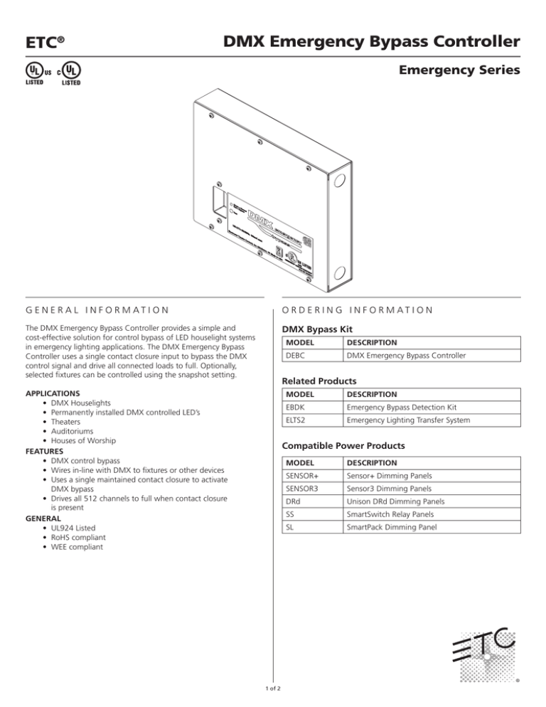
The DMX Emergency Bypass Controller provides a simple and
cost-effective solution for control bypass of LED houselight systems
in emergency lighting applications. The DMX Emergency Bypass
Controller uses a single contact closure input to bypass the DMX
control signal and drive all connected loads to full. Optionally,
selected fixtures can be controlled using the snapshot setting.
DMX Bypass Kit
MODEL
DESCRIPTION
DEBC
DMX Emergency Bypass Controller
Related Products
APPLICATIONS
• DMX Houselights
• Permanently installed DMX controlled LED’s
• Theaters
• Auditoriums
• Houses of Worship
FEATURES
• DMX control bypass
• Wires in-line with DMX to fixtures or other devices
• Uses a single maintained contact closure to activate
DMX bypass
• Drives all 512 channels to full when contact closure
is present
GENERAL
• UL924 Listed
• RoHS compliant
• WEE compliant
MODEL
DESCRIPTION
EBDK
Emergency Bypass Detection Kit
ELTS2
Emergency Lighting Transfer System
Compatible Power Products
1 of 2
MODEL
DESCRIPTION
SENSOR+
Sensor+ Dimming Panels
SENSOR3
Sensor3 Dimming Panels
DRd
Unison DRd Dimming Panels
SS
SmartSwitch Relay Panels
SL
SmartPack Dimming Panel
DMX Emergency Bypass Controller
ETC®
Emergency Series
S P E C I F I C AT I O N S
S P E C I F I C AT I O N S
FUNCTIONAL
• Overrides a single universe of ANSI E1.11–2008, USITT
DMX512-A control signals from “Normal” to “Bypass” when
a trigger signal is detected via a two-pin trigger input
• Polls the bypass trigger input after a power loss and reacts
upon start up
• Does not process DMX input in Normal mode (pass-through)
• Records a single DMX preset (snapshot) of 512 channels for
recall during “Bypass” mode
• Recalls default or recorded sequence immediately on restart if
the trigger is also applied at restart
MECHANICAL
• Enclosure constructed of 18-gauge, formed steel panels with
a removable front cover finished in gray, fine-textured powder
coat paint
• Designed for Wall-mount applications
• Internal voltage barrier provides separate wiring
compartments for power and control wiring
• LED indicator visible from the exterior of the enclosure.
-- Normal state with a “green” color light when Power
is present
-- Bypass state with a “red” color light when active
• Test button accessible from the front of the enclosure without
removing any panels
• The test button shall be recessed to prevent accidental
triggering
• Internally accessible, labeled DIP switches for configuration of:
-- DMX Record Mode
-- Contact input type
-- Wait Time for Restore incoming DMX (bypass
trigger removed)
• Internally accessible button for DMX Record (snapshot) with
an indicator LED for record action
ELECTRICAL
• Supports 100 to 277 volt input power, 50/60 Hz, .2 amp
maximum current
• Power Input terminals accept two 24 – 10 AWG solid or
stranded wires
• Grounding Lug accepts 14-2 AWG solid or stranded
ground wire
• Bypass Contact Input supports two, 30-12 AWG low-voltage
wires with two modes:
-- +12VDC sent from the DEBC through a remote
contact (dry)
-- +12VDC to +24VDC sent from the remote device to the
DEBC contact (wet)
• Bypass input configurable as Maintained Normally Open
(default) or Maintained Normally Closed
ELECTRICAL (CONTINUED)
• Supports one Universe (512 channels) of Digital Multiplexing
(DMX) in accordance with ANSI E1.11–2008,
USITT DMX512-A.
-- DMX Output and DMX Input terminals for Belden 9729
cable or equivalent
-- Socketed DMX transceiver chip with on-board spare
• Non-volatile memory for storage of a single recorded
sequence of 512 channels.
• UL and cUL 924 Listed for Emergency
Lighting applications.
THERMAL
• Ambient room temperature: 0-40°C / 32-104°F
• Ambient humidity: 10-90% non-condensing
PHYSICAL
DMX Emergency Bypass Controller Dimensions*
MODEL
HEIGHT
WIDTH
DEPTH
inches
mm
inches
mm
inches
mm
9.0
229
11.0
279
2.0
52
DEBC
DMX Emergency Bypass Controller Weight*
MODEL
WEIGHT
DEBC
SHIPPING WEIGHT
lbs
kgs
lbs
kgs
4.7
2.2
5.4
2.5
*Weights and dimensions typical
Top View
Front View
Side View
(Cover Panel Removed)
2.0”
52mm
CR2
CR3
R21
+5VISO
TP4
R10
R15
C25
C26
SWITCH 1 - MODE
SWITCH 2 - PANIC INPUT
OFF = ALL FULL MODE
OFF = NORMALLY OPEN
ON = RECORD MODE
ON = NORMALLY CLOSED
SWITCH 3
SWITCH 4
PANIC EXIT DELAY
OFF
OFF
0 SECONDS
C8
U3
PANIC IN
IN
ON
10 SECONDS
ON
OFF
30 SECONDS
ON
ON
10 MINUTES
L
C41
C42
C40
9.0”
229mm
VR3
C35
C32
L3
+ C36
R27
C38
C34
R24
C43
C37
CR11
R28
R26
+5V
TP5
U9
T1
CR6
C22
R25
C31
R23
C30
L1
C33
CR8
VR2
R22
+
C29
VR1
C23 CR5
+12V
TP6
C21
CR9
TP2
GND
TP3
TESTPOINT STATUS
C27
LD2
S4
C24
R4
C3
R11
R13
R14
R17
C16
R16
J2
VOUT
R20
R12
RESET
U6
C11
C12
C15
C1
RECORDC20 C19
C10
U5
C14
R8
R18
S3
J3
CDI
S1
R19
S2
1 2 3 4
OFF
L2
R29
CR4
C6
CONFIG
TEST
J6
J4
BKGD
+
R7
U4 R9
U8
NORMAL/PANIC
LD1 R1
AC INPUT
F1
0.5A
TH1
CONFIG SWITCHES
U7
XU7
K2
TP1
GNDISO
C4
R6
U1
Q2
K1
C28
R5
C2
R3
SPARE
Q1
U2
XU2
R2
7180B4641 REV.A
2011 ETC, INC.
MADE IN THE U.S.A.
ASSEMBLY
I.D. LABEL
DMX IN
J5
CR1
CR7
DMX+
N
DMX+
COM
DMX-
COM
DMX OUT
J1
DMX-
C5
C7
C9
C13
C17
C18
11.0”
279mm
CR10
C39
COM
JP2
.875
1/2” KO
space for up to 1”
Corporate Headquarters • 3031 Pleasant View Rd, PO Box 620979, Middleton WI 53562 0979 USA • Tel +1 608 831 4116 • Fax +1 608 836 1736
London, UK • Unit 26-28, Victoria Industrial Estate, Victoria Road, London W3 6UU, UK • Tel +44 (0)20 8896 1000 • Fax +44 (0)20 8896 2000
Rome, IT • Via Pieve Torina, 48, 00156 Rome, Italy • Tel +39 (06) 32 111 683 • Fax +44 (0)20 8752 8486
Holzkirchen, DE • Ohmstrasse 3, 83607 Holzkirchen, Germany • Tel +49 (80 24) 47 00-0 • Fax +49 (80 24) 47 00-3 00
Hong Kong • Room 1801, 18/F, Tower 1 Phase 1, Enterprise Square, 9 Sheung Yuet Road, Kowloon Bay, Kowloon, Hong Kong • Tel +852 2799 1220 • Fax +852 2799 9325
Web • www.etcconnect.com • Copyright©2012 ETC. All Rights Reserved. All product information and specifications subject to change. 7180L1040 Rev. C USA 03/12
2 of 2


