Homework #1
advertisement

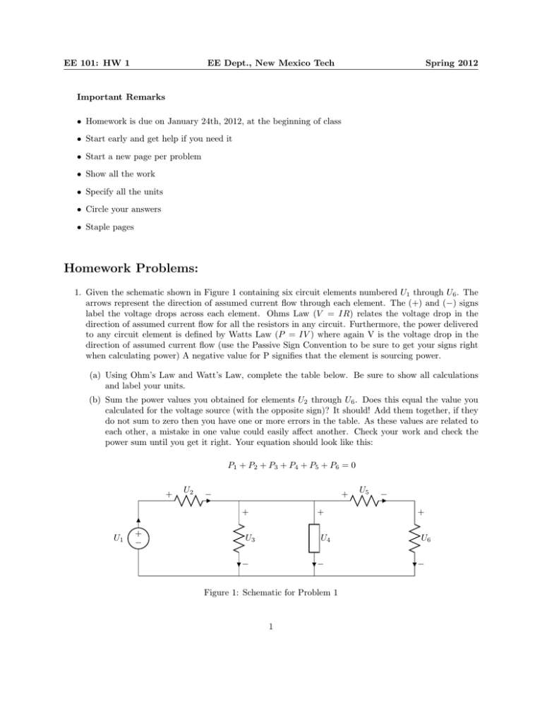
EE 101: HW 1 EE Dept., New Mexico Tech Spring 2012 Important Remarks • Homework is due on January 24th, 2012, at the beginning of class • Start early and get help if you need it • Start a new page per problem • Show all the work • Specify all the units • Circle your answers • Staple pages Homework Problems: 1. Given the schematic shown in Figure 1 containing six circuit elements numbered U1 through U6 . The arrows represent the direction of assumed current flow through each element. The (+) and (−) signs label the voltage drops across each element. Ohms Law (V = IR) relates the voltage drop in the direction of assumed current flow for all the resistors in any circuit. Furthermore, the power delivered to any circuit element is defined by Watts Law (P = IV ) where again V is the voltage drop in the direction of assumed current flow (use the Passive Sign Convention to be sure to get your signs right when calculating power) A negative value for P signifies that the element is sourcing power. (a) Using Ohm’s Law and Watt’s Law, complete the table below. Be sure to show all calculations and label your units. (b) Sum the power values you obtained for elements U2 through U6 . Does this equal the value you calculated for the voltage source (with the opposite sign)? It should! Add them together, if they do not sum to zero then you have one or more errors in the table. As these values are related to each other, a mistake in one value could easily affect another. Check your work and check the power sum until you get it right. Your equation should look like this: P1 + P2 + P3 + P4 + P5 + P6 = 0 + U2 − + + − + U1 + U3 U4 − − Figure 1: Schematic for Problem 1 1 U5 − + U6 − EE 101: HW 1 Element # U1 U2 U3 U4 U5 U6 EE Dept., New Mexico Tech Voltage 5V Current 2A 2A 3V 3V 2V 0.5A 0.5A Resistance N/A 1Ω 3Ω N/A 2Ω Power 4W 1.5W Spring 2012 Element Type Voltage source Resistor Resistor Mystery component Resistor Resistor The voltage source is sourcing power to the circuit, so P1 should be a negative number. The rest of the elements are dissipating power, so their power values should be positive. This is not an arbitrary assignment - the actual value, if calculated properly should be either positive or negative, which tells you whether the component is sourcing or dissipating energy. Because this is a simple circuit we generally assume that a source is providing power and a resistor is consuming it. However, it is not always that easy to tell. Later we will study circuit components where we are not sure if it is sourcing or dissipating power until we make that calculation and look at the sign, so it is very important to learn to do this calculation correctly. The sum of elements dissipating power and the sum of the elements delivering power must together sum to zero. In this case the power supplied is equal to power dissipated which demonstrates Conservation of Power, which should be true for any circuit. (c) This circuit defines a total of six loops. The first three are fairly obvious (U1 + U2 + U3 , U3 + U4 , U4 + U5 + U6 ). A big loop can be made of the outer elements (U1 + U2 + U5 + U6 ), and two more loops made by combining the left and middle loops (U1 + U2 + U4 ) and the middle and right loops (U3 + U5 + U6 ). Look at the element voltages for each loop and confirm that Kirchoffs Voltage Law (KVL) is true for this circuit. Write an equation for each loop to sum the voltages around it, and see that each loop sums to zero. Remember that we sum voltage drops in the direction of assumed current flow, so there should be some negative values in your equations. For example, the loop equation defined by U1, U2, and U3 should look like this: U1 + U2 + U3 = 0 −5 + 2 + 3 = 0 0=0 KVL is validated. (d) U3 and U4 are elements that are said to be connected in parallel because they are connected to each other at both ends. In this circuit, are there other elements connected in parallel? If so, identify the element combinations that make parallel connections. (e) Looking at the voltage drops in the table, what can be said, in general, about the voltages across parallel circuit elements? Use KVL to prove your theory. (f) U1 and U2 are elements that are connected in series because they are connected to each other at only one terminal and no other elements connect to that same terminal. Does this circuit contain other elements connected in series? If so, identify the element combinations that make series connections. (g) Looking at the current column of the table, what can be said generally about the current flowing through series elements? Use Kirchoffs Current Law (KCL) to prove your theory (think of the connection point as a node). 2 EE 101: HW 1 EE Dept., New Mexico Tech Spring 2012 Is I1 + Vs ≡ 20V V1 I2 + R1 ≡ 5Ω − V2 R2 ≡ 10Ω − Figure 2: Schematic for Problem 2 2. Using the schematic provided in Figure 2 (a) Using your knowledge of voltages across parallel elements (based on KVL), determine the value of V1 and V2 . (b) Using your knowledge of Ohms Law, along with your answers from part a, determine the current through R1 and R2 . (c) KCL states that the sum of all currents entering a node (or the sum of the currents leaving a node) must equal zero. An equivalent statement is to say that the sum of all currents entering a node must equal the sum of all currents leaving the node. Apply KCL, and your answers from part b, to find Is . (d) Determine the power dissipated by each of the resistors and the power sourced by the voltage source. Use these numbers to show that power is conserved. 3. In class we drew a schematic diagram for a flashlight. Similarly: (a) Draw and properly label a schematic for a cars headlight circuit, using the symbols for a battery (DC voltage source), switch, and resistors (to represent the lamps). Assume the battery is 12 volts. A correct design ensures that if one lamp burns out the other will stay lit. Think about KVL and KCL to get this right. (b) When the lights are turned on and one headlight is burned out (there is no current flow through the lamp), why does the other headlight still work? Use the tools we have practiced to explain your answer (KVL, KCL, OL). 3


