Quick End Launch (QEL SMA)
advertisement

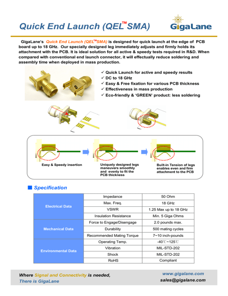
TM Quick End Launch (QEL SMA) GigaLane’s Quick End Launch (QELTMSMA) is designed for quick launch at the edge of PCB board up to 18 GHz. Our specially designed leg immediately adjusts and firmly holds its attachment with the PCB. It is ideal solution for all active & speedy tests required in R&D. When compared with conventional end launch connector,it will effectually reduce soldering and assembly time when deployed in mass production. ü Quick Launch for active and speedy results ü DC to 18 GHz ü Easy & Free fixation for various PCB thickness ü Effectiveness in mass production ü Eco-friendly & ‘GREEN’ product: less soldering Easy & Speedy insertion Uniquely designed legs maneuvers smoothly and evenly to fit the PCB thickness Built-in Tension of legs enables even and firm attachment to the PCB ■ Specification Electrical Data Mechanical Data Environmental Data Impedance 50 Ohm Max. Freq. 18 GHz VSWR 1.25 Max up to 18 GHz Insulation Resistance Min. 5 Giga Ohms Force to Engage/Disengage 2.0 pounds max. Durability 500 mating cycles Recommended Mating Torque 7~10 inch-pounds Operating Temp. -40℃~125℃ Vibration MIL-STD-202 Shock MIL-STD-202 RoHS Compliant Where Signal and Connectivity is needed, There is GigaLane www.gigalane.com sales@gigalane.com TM Quick End Launch (QEL SMA) ■ Part number & Board clearance Part No. Board Clearance PSF-S06-000 0.25 ~ 1.2 mm PSF-S06-001 1.25 ~ 2.0 mm ※ As described in the table,2 product specifications are available to accordingly cover all common PCB thicknesses. ■ Drawing & PCB pattern PSF-S06-000 Recommended PCB Mount PSF-S06-001 Unit : mm ■ Performance <DUT> Connector - PSF-S06-000: 2ea PCB - FR4 Sub Thickness : 0.6 mm - 50 Ω Line Width : 1.2 mm - Line Length : 18 mm Where Signal and Connectivity is needed, There is GigaLane www.gigalane.com sales@gigalane.com TM Quick End Launch (QEL SMA) ■ Soldering Guide QEL Connector must be launched on the center of PCB while moving such as arrow direction. ■ Soldering Flow & Notice 1. Center Conductor Soldering 1. When center pin soldering, must not be soldered to internal QEL SMA. before after 2. Top Ground Plate Soldering 2. Must be soldered to internal QEL SMA Clip. 3. When soldering, Signal & GND must be separated. 4. Must be careful Cold Soldering. before after 3. Bottom Ground Plate Soldering before after Where Signal and Connectivity is needed, There is GigaLane www.gigalane.com sales@gigalane.com

