CAPITAL CONTROLS®
SERIES HIGH CAPACITY
NXT3000
1,000 - 3,000 PPD (20-60 KG/H)
Proven design, rugged construction, and
the use of the best available materials
assures precise gas feeding, low
maintenance and dependable operation
for the life of the equipment.
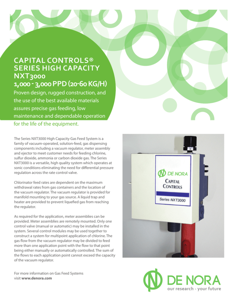
The Series NXT3000 High Capacity Gas Feed System is a
family of vacuum-operated, solution-feed, gas dispensing
components including a vacuum regulator, meter assembly
and ejector to meet customer needs for feeding chlorine,
sulfur dioxide, ammonia or carbon dioxide gas. The Series
NXT3000 is a versatile, high quality system which operates at
sonic conditions eliminating the need for differential pressure
regulation across the rate control valve.
Chlorinator feed rates are dependent on the maximum
withdrawal rates from gas containers and the location of
the vacuum regulator. The vacuum regulator is provided for
manifold mounting to your gas source. A liquid trap and
heater are provided to prevent liquefied gas from reaching
the regulator.
As required for the application, meter assemblies can be
provided. Meter assemblies are remotely mounted. Only one
control valve (manual or automatic) may be installed in the
system. Several control modules may be used together to
construct a system for multipoint application of chlorine. The
gas flow from the vacuum regulator may be divided to feed
more than one application point with the flow to that point
being either manually or automatically controlled. The sum of
the flows to each application point cannot exceed the capacity
of the vacuum regulator.
For more information on Gas Feed Systems
visit www.denora.com
We Understand
Disinfection
When automatic control is required a Chloromatic™ valve can
be provided which will respond to control signals from a water
flow transmitter and/or chlorine residual analyzer controller.
Design Features
Several vacuum source choices are available for the Series
NXT3000 system. The 2” flanged ejectors (3” for 3000 PPD)
and EJ17 for ammonia can be used for general applications.
These incorporate a back-flow check valve and an emergency
overflow drain valve within the ejector which prevents water
or process liquid from entering the gas (vacuum) line when
the ejector is not operating. In addition, a CHLOR-A-VAC®
chemical induction unit can be used as the vacuum source for
the system.
–Modularity: System consists of vacuum regulator, meter assembly and ejector.
For applications requiring uninterrupted gas feed, a built-in
automatic changeover function is provided in
every vacuum regulator. All that is required is two vacuum
regulators. No separate changeover module or valve is
required.
Only one vacuum regulator is required to feed maximum
capacities up to 3,000 PPD (60 kg/h) for chlorine. Units similar
to those for feeding chlorine but with different materials of
construction are available for feeding sulfur dioxide – max
capacity 2,000 PPD/40 kg/h (capacity limited by metering
tube, vacuum regulator can feed up to 3,000 PPD) ; ammonia
– max capacity 1,000 PPD (20 kg/h); Carbon Dioxide – max
capacity 1,500 PPD (30 kg/h). The maximum feed capacity is
dependent on the gas source.
2 De Nora Water Technologies
–Modern Design: Operates on the sonic principle. No D/P
regulation required. Fewer parts mean better reliability and
improved ease of maintenance.
–Inlet Valve Body and Spring: Both are manufactured from
Hastelloy-C and warranted for life.
–Control Signals: The Chloromatic valve insures positive
response to electrical signals representing either water flow
or chlorine residual control. Optionally, both flow pacing and
residual control signals can be accepted simultaneously by
the Chloromatic valve.
–Versatility: System adapts to automatic vacuum changeover
by simply adding a second vacuum regulator. No separate
changeover module required.
–Safe Operation: All vacuum operation prevents escape of
gas to atmosphere.
–Minimum Maintenance: Simple design minimizes routine
maintenance. PM kits available for all major components.
Engineering Specifications
Capacities: Standard metering tubes are available with the
following maximum capacities: 1000, 2000 and 3000 PPD
(20, 40 and 60 kg/h) of chlorine gas. Metering tubes have
dual scales in English and metric units. Any combination of
capacities may be used on multiple feed point applications as
long as the total does not exceed the capacity of the vacuum
regulator.
Automatic Changeover: Two vacuum regulators are used in
an automatic changeover system. Either vacuum regulator is
selected by the station operator, allowing gas to flow until the
chlorine source is exhausted. At that point, the second vacuum
regulator opens to allow gas feed to continue. Each regulator
has an indicator to show whether it is in “Reserve”, “Operating”,
or a “Empty” condition.
Flowmeter Rangeability: 20 to 1 for any one metering tube.
Scale length for all capacities is 10 inches (25.4 cm) for easy
readability. All tubes for chlorine, sulfur dioxide and ammonia
are direct reading.
Control Modes: The gas feeder can be controlled either
manually or automatically by the use of a rate control valve.
For a manual control application, a manual rate control valve is
provided as part of the meter assembly. For automatic control
a separate control valve (The Chloromatic Valve – see below) is
provided.
Ejector Requirements: Water passing through the ejector
generates the vacuum required to operate the chlorinator.
Water consumption and required inlet pressure are dependent
on the amount of chlorine being fed and the ejector back
pressure. Water passing through the ejector must be
reasonably clean. If high temperature water is used, (above
80°F/26°C), ejector performance will be impaired due to
decreased solubility of the gas. Reference should be made to
pipe manufacturer’s product literature for decreased pressure
ratings of PVC piping. Ejectors provided can handle back
pressures up to 200 psig (1380 kPa) depending on capacity.
The ejector is wall mounted and is supplied with a check valve
and an emergency drain connection to prevent water from
reaching the vacuum regulator.
Mounting: The vacuum regulator is wall or manifold mounted.
The unit is protected from liquid chlorine damage (up to the
volume of one full ton container eductor tube) by means of
a combination manifold trap filter assembly. Trapped liquid
chlorine is vaporized by a 25W electric heater. Automatic
control valves (Chloromatic™) are furnished separately for
direct wall mounting. The manifold contains a 5.9 sq. in., 0.01
micron cartridge filter.
Chloromatic Valve: The Chloromatic valve has two major
components: the control valve and the control valve operator.
Two versions of the operator are available; one for a single
input signal and one for dual input signals. The single input
valve operator can be adapted to respond to any one of the
following signals: 4-20, 0-16, or 0-20 mAdc; 1-5, 0-4, or 0-5
Vdc (normally from a flow transmitter). The dual input valve
operator is designed to respond to any two of the signals listed
above. Normally, the second signal is from a chlorine residual
controller. Temperature limits on the Chloromatic valve are 20
to 125°F (–7 to +52°C). Reference bulletin 100.0310 for more
information.
Options: Include a gas pressure gauge and a low temperature
switch to sense liquefied gas presence having contacts rated
at 10W, 120V max.
De Nora Water Technologies 3
We Understand
Disinfection
Connections:
Vacuum Regulator:
Gas Outlet: 1” NPTE PVC
Vent: ¼” NPT X 5/8” OD tubing
Meter Assembly:
Gas Inlet and Outlet: 1” FNPT
2” Ejector up to 2000 PPD (40kg/h) as chlorine:
Water inlet: 2” threaded (female)
Solution outlet: 2” threaded (male)
Gas vacuum inlet: 1” NPT union
Emergency drain: ¾” NPT or 1” hose
3” Ejector, 2000-3000 PPD (40-60 kg/h) as chlorine:
Water inlet and solution outlet: 3” flanged
Gas vacuum inlet: 1-1/2” NPT union
Emergency drain: ¾” NPT or 1” hose
EJ17, up to 500 PPD - as chlorine:
(not for ammonia service)
Water inlet: 1” NPT
Solution outlet: 3/4” NPTE or 1” hose
Gas Vacuum inlet: 5/8” tubing
Emergency drain: 5/8” tubing
Electrical Requirements:
Heater furnished with a 6-foot (1.8 M) cord for either 120 Vac
(plug) or 240 Vac (hardwired). Heater is 25W and requires 0.21
A at 120 Vac or 0.10 A at 240 Vac. Chloromatic valve requires
0.3A at 120 Vac or 0.15A at 240 Vac
Materials of Construction: See Bulletin 100.3201.
Temperature Limits:
Ambient maximum: 130°F (54°C)
Ejector water maximum: *100°F (38°C)
Normal vacuum regulator operating range: 38 - 130°F (2-54°C)
–Ejector performance will be impaired due to decrease in gas
solubility if water temperature is above 77°F (25°C).
4 De Nora Water Technologies
Shipping Weight:
Dimensions
Shipping Weight
Volume
Vacuum Regulator
7 lb (3.2 kg)
1.7 cu.ft. (0.05 m3)
Liquid Trap
7 lb (3.2 kg)
1.0 cu.ft. (0.03 m3)
Meter Assembly
12 lb (5.4 kg)
1.0 cu.ft. (0.03 m3)
Ejector, 2” or 3”
10 lb (4.5 kg)
2.0 cu.ft. (0.06 m3)
Ejector, EJ17
3 lb (1.5 kg)
1.0 cu.ft. (0.03 m3)
Accessories:
Standard:
1 - Ammonia leak test bottle
1 - Insect screen for vent line
4 - Spare lead gaskets
1 - Multipurpose wrench
1 - Instruction bulletin and parts list
Options:
Gas Pressure gauge
Out of gas alarm switch
Preventative Maintenance Kits
Chloromatic valve (100.0310)
Chloralert Plus™ Chlorine Gas Detector (Bulletin 325.0025)
MicroChem®2 Series 4000 Chlorine Residual
Analyzer (Bulletin 210.0100)
VEGA - Vent Exhaust Gas Arrestor (141.0001)
Description of Operation
The chlorine gas from the source enters the manifold where
it is filtered to remove any foreign material which might be
present. Water flowing through the ejector creates a vacuum
which opens the inlet valve of the vacuum regulator to admit
the gas into the regulator. A diaphragm regulates the vacuum
at this point to a closely controlled value.
The gas passes through the flowmeter(s) and the rate control
valves (either manual or automatic) and then goes to the
ejector or ejectors where it is thoroughly mixed and dissolved
in the motive water and carried to the application point as a
solution. When multiple metering tubes and ejectors are used,
each operates independently of the others. Adjustment of one
of the gas flow rates has no effect on the other rates.
At the same time, an indicating lever on the side of the
vacuum regulator shows that the gas supply has been
exhausted.
When the vacuum regulators are used in an automatic
changeover system, either vacuum regulator is selected by
the station operator allowing gas to flow until the chlorine
source is exhausted. At that point, the second vacuum
regulator automatically opens to allow gas feed to continue.
Each regulator has an indicator to show whether it is in the
“RESERVE”, “OPERATING”, or “EMPTY” mode.
The system is completely under vacuum from the ejector to
the gas inlet valve during operation. If the water supply to
the ejector is stopped, or the operating vacuum is lost for any
other reason, the spring-loaded gas inlet valve immediately
closes to isolate the chlorinator from the gas supply. Any gas,
under pressure, which might enter the regulator, is vented
from the system through the built-in pressure relief valve. If
the source of chlorine gas is exhausted, the gas port closes to
prevent excessive vacuum levels from developing upstream
of the vacuum regulator and also prevents any moisture from
being drawn back into the operating components or the gas
supply lines.
De Nora Water Technologies 5
We Understand
Disinfection
EJ17
EJECTOR
(NOT FOR
AMMONIA SERVICE)
METER
ASSEMBLY
2 INCH
EJECTOR
3 INCH
EJECTOR
Additional System Components
6 De Nora Water Technologies
AUTOMATIC
GAS CONTROL
VALVE
CHLOR-A-VAC
CHEMICAL
INDUCTION UNIT
Brief Description
The gas feed system shall be a vacuum-operated, solution feed
type with a feed range of___ to ___ PPD of _____ gas. It shall
be of the sonic flow design.
The vacuum regulator shall be suitable for wall mounting
and shall be provided with an integrally mounted manifold
trap with built-in electric heater with ten foot cord. Power
requirement shall be 120 Vac or 240 Vac, 50/60 Hz. The
manifold shall have a 5.9 square inch, removable filter
cartridge having a 0.01 micron pore size.
A positive tight shut-off valve with Hastelloy®C body shall
be provided within the vacuum regulator to isolate gas
under pressure from the control system should there be a
loss of vacuum. A spring-loaded pressure relief valve shall
be provided to prevent the build-up of pressure within the
gas control system. An excess vacuum shut-off valve shall
be provided as an integral part of the vacuum regulator to
automatically isolate the regulator from the meter assembly
and ejector on loss of gas supply pressure. Provisions for
automatic changeover shall be incorporated within the
vacuum regulator without the need for an external valve. An
indicator shall provide visual indication when the chlorine gas
supply is exhausted or interrupted.
A meter assembly having a 20:1 range shall be provided to
indicate the gas feed rate. The meter shall be calibrated for the
gas being fed and shall be direct reading in both English and
metric units and the meter scale shall be 10 inches (25.4 cm). It
shall be suitable for mounting on the wall. It shall be provided
with a manual rate valve for manual control. When the system
is automatically controlled no manual valve is provided. When
required for automatic operation a Chloromatic™ control valve
shall be provided (reference bulletin 100.0310 for equipment
description).
An ejector shall be furnished with the system. The ejector
nozzle and throat shall be sized for the application and have
a check valve and emergency drain valve to prevent water or
solution from flooding the chlorinator. The ejector shall be
designed for the following conditions:
Water supply pressure: _____psig
Maximum water flow: _____gpm
Maximum back pressure: _____psig
The vacuum regulator, meter assembly, rate control valve
(manual or automatic), and ejector assembly shall be
manufactured from materials resistant to corrosion from the
chemicals being fed. All components shall be manufactured
in a facility certified to meet the requirements of ISO9001
International Standards.
The following accessories shall be supplied: Insect screen,
bottle for test solution, four spare lead gaskets, universal
wrench, thread lubricant, and instruction manual and parts list.
The gas feed system shall be De Nora Water Technologies
Series High Capacity NXT3000, or approved equal.
Option: VEGA - Vent Exhaust Gas Arrestor
Refer to product bulletin 141.0001
De Nora Water Technologies 7
www.denora.com
® Registered Trademark. © 2015. All Rights Reserved.
105.0060.5
T: +1 215 997 4000
F: +1 215 997 4062
E:info.dnwt@denora.com
SEP 2015
De Nora Water Technologies
3000 Advance Lane
Colmar, PA 18915
United States


