AV-26 Power Supply & Charger
INSTALLATION INSTRUCTIONS
Item: 4728_26 (A5DS)
Description
The AV-26 is a 12V DC -13A, 12 channels central Power Supply and Charger with battery
monitor, provides the extra power for CCTV cameras, alarm, access control and other
large installations with devices that operate on 12V DC. The AV-26 dramatically improves
the video quality in CCTV installations.
The AV-26 is enclosed in ABS box, metal box is optional. AV-26 is including Battery
Monitor and Charger. The AV-26 protects the battery with the Battery Monitor circuitry:
Not allows totally discharged, overcharge and wrong polarity wiring.
Ordering: AV-26 12 outputs, AV-26F 13 output including 5V for Wi-Fi router.
Installation Instructions
-
ry
tte
Ba
DC Supply
Input
-V IN
+V IN
L N
Hi
VOLTAGE
C
B
E
E
B
C
E
B
C
C
B
E
Main 220V AC To metal power unit
High voltage
Switch
+
Fail LED and
output
Re
d
wir
e
FA12
to
+
of
b
att
e
ry
Ooption: 5V for router
Model AV-26F
Attention! High voltage; disconnect main AC prior to install and service
Attention! Fire risk; Verify battery polarity before, wrong polarity cause fire
The AV-26 supply maximum 13A in total. Output 1 is for DVR or camera
The Switching Power Supply metal case is HOT under full load, don’t cover!
Install the AV-26 to wall with ventilation slot upwards! Do not lay the box!
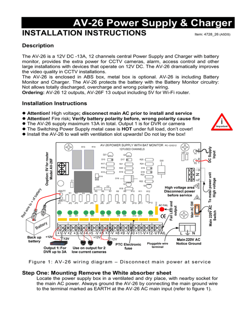
F i g u r e 1 : A V - 2 6 wi r i n g d i a g r a m – D i s c o n n e c t m a i n p o we r a t s e r vi c e
Step One: Mounting Remove the White absorber sheet
Locate the power supply box in a ventilated and dry place, with nearby socket for
the main AC power. Always ground the AV-26 by connecting the main ground wire
to the terminal marked as EARTH at the AV-26 AC main input (refer to figure 1).
Step Two: Wiring Main AC
The AV-26 operates on 115V or 220V AC. The factory setting is for 220V. For 115V mode
set the internal selector on the switching power supply and switch to 115V.
Connect the ground first (refer to figure 1) “N” and “L” wires to the two “AC Main” terminals.
The switching power supply is factory interfaced to the AV-26 main board.
Step Three: Wiring DVR and Cameras
Only output 1 is compatible with DVR that powered by 12 volts, maximum 2.8A, or
camera. Outputs numbered 2 to 12 are for cameras powered by 12V maximum 1.1A.
Power-up without battery, before wiring DVR and/or CCTV cameras, and battery
connection, verify that all output channels Green LEDs are on.
Power-down the AV-26, push the main switch (right side) to Off. The Green LED per
channel indicated Power status, to disconnect the channel power remove the channel’s
Jumper accordingly.
Wire-up the loads (DVR, cameras) in the correct polarity; Positive to the +V and Negative
to the –V terminals, power up and verify the Green LED is on, make sure the powered
items well operate.
Fail Output: If the main power supply voltage is low or fail the Red LED turns on with –V
applied to the FAIL terminal, this FAIL can trig buzzer or dialer that consume 100 mA
maximum. For 16 cameras site connect two cameras to same channel (each channel is
1.1A maximum), refer to figure1.
Note 1: The AV-26 is factory adjusted at approximately 13.8V (supply 10A) to allow the
12V long wiring, for higher current lower the output voltage to 12.8V get higher current
(12A). To lower the voltage: Apply a voltmeter and gently tune the trimmer (located on the
metal main power supply).
Connect the Battery Red wire to + (Positive) battery terminal and the Black wire to the –
(Negative) battery terminal.
The AV-26 is compatible with SLA type rechargeable battery. Use 12V 4 to 9 A/H battery.
The AV-26 loads are electronically protected by a solid-state fuse and over current
circuitry build-in the regulator. In case of failure touch the fuse enclosure (Yellow color) for
over heating. Hot electronic fuse means over loading. Disconnect the channel’s Jumper
and find the overloading item, most caused by wires short or faulty camera/DVR.
In case one or few channels are overloaded the fuse disconnect them automatically, but
the overloaded channels consumes the limited current, disconnect them to prevent over
heating of the whole power supply. Attention! Before service disconnect main AC
EasyLoader applications & Electronic Fuse
When connecting the AV-26 to EasyLoader control panel (fail output activate the
dialer, or other alerts), connect the –V (common minus) from AV-26 and the –V
of the control panel.
Operating Temp: -10 to +60 C°
Humidity: 80%
AC Input: 220V or 115V AC
AC Input: Pluggable terminal
AC Fuse: Inside main power unit
Power supply: Switching 150W
Ripple at 1A load: 15 mV, P-P
AV-26 Specifications
Battery monitor cut: @ 9.9 V
DC Output: 13.8V DC, +/- 8%
Max. DC Current per channel: 1A
Protection: Thermal fuse 12 pc's
Polarity Protection: Electronic
Fail level output: 11.8V +/- 3%
Fail Indicator: Red LED
® All rights reserved to Av-Gad Systems Ltd, AV-26 MANUAL ENG.DOC, August 2015
Power Indicator: Green LED
DC Wiring: Screws Terminals
Battery charge max: 1.5A
Battery charge voltage: 13.6V
Battery Size: 12V- 7.2 or 9 AH
Battery Type: SLA
Box size: 230 x 310 x 60 (mm)


