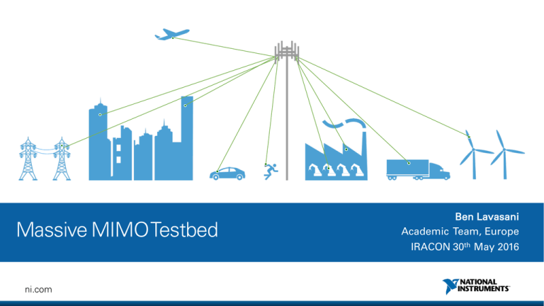
Massive MIMO Testbed
advertisement

Massive MIMO Testbed Ben Lavasani Academic Team, Europe IRACON 30th May 2016 ni.com Our Mission We equip engineers and scientists with the systems that accelerate productivity, innovation, and discovery. ni.com Our Customers Industrial Machinery Aerospace and Defense Electronics and Semiconductor Academic and Research Wireless Transportation and Heavy Equipment Automotive Energy ni.com ITU-R Vision for 5G >10 Gb/s Peak Rate 100 X More Devices ni.com mMTC eMBB uMTC, UR/LL < 1 mS Latency Prototyping is Critical for Wireless Research “Investigation, prototypes, technology demos and pilots of network management and operation, cloud-based distributed computing and big data for network operation. Extension of pilots and trials to non ICT stakeholders to evaluate the technical solutions and the impact in the real economy. Detailed standardisation process based on validated system concepts by means of simulations and close to real world trials.” 1 15GPPP Vision - http://5g-ppp.eu/wpcontent/uploads/2015/02/5G-VisionBrochure-v1.pdf ni.com 5G Vectors in Need of Prototyping Massive MIMO mmWave Dramatically increased number of antenna elements on base station enabling beamforming. Utilize potential of extremely wide bandwidths at frequency ranges once thought impractical for commercial wireless. ni.com Multi Radio Access Technologies (RAT) Improve bandwidth utilization through evolving PHY Level and flexible numerology Wireless Networks Consistent connectivity meeting the 1000x traffic demand for 5G • Densification • SDN • NFV • CRAN 5G Vectors in Need of Prototyping Massive MIMO mmWave Dramatically increased number of antenna elements on base station enabling beamforming. Utilize potential of extremely wide bandwidths at frequency ranges once thought impractical for commercial wireless. ni.com Multi Radio Access Technologies (RAT) Improve bandwidth utilization through evolving PHY Level and flexible numerology Wireless Networks Consistent connectivity meeting the 1000x traffic demand for 5G • Densification • SDN • NFV • CRAN Massive MIMO • Give base station a large array of antennas • • Increase capacity 10x and energy efficiency 100x • • • • More robust to individual chain failure and process variation Significant latency reduction of the air interface • • Power amplifier requirements are relaxed Potential for lower peak-to-average power ratio waveforms Can be built with inexpensive, lower power components • • > 10X higher than current systems Low-latency needed for time-division duplexing Simplifies the medium access control layer Increases robustness to interference and jamming T. L. Marzetta, “Noncooperative cellular wireless with unlimited numbers of base station antennas,” IEEE Trans. Wireless Comm., vol. 9, no. 11, 2010. ni.com Massive MIMO / FD MIMO: Theoretical 10X Capacity Gain Prototyping is needed. Phased Array … Phased Array 8 Transceiver Base Station 64 Transceiver Base Station Approach 1: Hybrid Beamforming 3-5x est. capacity Approach 2: Digital Beamforming 10x est. capacity ni.com Practical Implications of Massive MIMO 3 128 Element Linear Dipole Array • 750 MHz = 12.8m wide • 3.5 GHz = 2.75m wide ¼λ ¼λ Patch Dipole ni.com Figure 1: Some possible antenna configurations and deployment scenarios for a massive MIMO base station. feed them back to the base station. This will not be feasible in massive MIMO systems, at least not when operating in a high-mobility environment, for two reasons. First, optimal downlink pilots should be mutually orthogonal between the antennas. This means that the amount of timeneeded for downlink pilots scales as the number of antennas, so a massive Source: Building frequency image from Rusek,resources et al “Scaling up MIMO: Opportunities and Challenges with Very Large Arrays,” IEEE Signal Processing Magazine MIMO system would require up to a hundred times more such resources than a conventional Universities of Bristol & Lund claim world record in spectral efficiency, demonstrating 145.6 bits/s/Hz | NI CONFIDENTIAL 11 NI and Samsung Demonstrate FD-MIMO With LabVIEW Communications and LTE App Framework NIWeek 2015 “Samsung Demonstrates FD-MIMO In Real Time For The First Time In The World…It Accelerates Its Leadership Over Competition For 5G Standard” english.etnews.com | NI CONFIDENTIAL 12 NI MIMO Prototyping Platform ni.com What is the MIMO Prototyping Platform Used For? Real-time prototyping of 5G Wireless Systems Develop New Algorithms ni.com Real-time Prototyping Get Real Results Fast Q2 2016 MIMO Prototyping Platform The world’s first real-time Massive MIMO testbed with software reference design and hardware that scales from 4-128 antennas. Applications •Cellular •Wi-Fi Capabilities •4-128 antennas •50 MHz – 6 GHz •20 MHz bandwidth •Real-time 2-way communication •Up to 12 simultaneous UEs ni.com 16 Channel Mini-Massive MIMO Demonstrator The Radio: USRP RIO 294XR / 295XR • 2 RF Frontends and 1 Kintex 7 FPGA per USRP RIO • 2x2 MIMO Support • RF Front Ends are available in different RF bands • • • • USRP RIO 2940R : 50 MHz to 2.2 GHz USRP RIO 2942R : 400 MHz to 4.4 GHz USRP RIO 2943R : 1.2 GHz to 6 GHz x4 MXI Cable with 830 MB/s throughput in each direction ni.com Clock and Timing: CDA-2990 (OctoClock) • 8-channel clock and timing distribution module • Amplify & split external 10 MHz reference & PPS (pulse per second) signal 8-ways • Matched-length traces • Optional internal GPS Disciplined Version for internal time and frequency reference • Ensures Phase Coherence between USRP RIOs (needed for most MIMO applications) ni.com Data Aggregation: CPS-8910 PCIe Switchbox • Combines 8 PCIe connections into a single stream • 3.2 GB/s data rate through PCIe x8 Gen 2 connection • Enables peer-to peer streaming between USRP RIOs ni.com The FPGA Co-processors : FlexRIO 7976R • Large Xilinx Kintex 7 410T FPGA • Resources available are • • • 64k slices 508k flip-flops 1540 DSP48 slices • 2.4 GB/s bidirectional throughput • 32 simultaneous high throughput connections to other FPGAs • Used for Data aggregation and Co-processing on FPGA • FPGA speed enables DSP to be done in-line ni.com The Host: PXIe 1085 Chassis • Industrial form factor 18 Slot Chassis • Gen 3 x8 PCIe backplane • 7 GB/s bidirectional throughput per Slot • Interconnection of chassis via MXI x8 or x16 cables • 6674T Timing and Synchronization Module for clock sync • 8384 PCIe Control Card to connect to USRP RIOs ni.com 8374 8374 8374 8374 7976R 7976R 6674T 7976R 7976R Host PXI Chassis 8374 8374 8374 8374 8135 128 Channel System Master Distribution CDA-2990 Slave CDA-2990 Slave CDA-2990 PCIe Switchbox PCIe Switchbox ... 8USRPs USRP 1-8 RIO ... 8USRPs USRP 9-16 RIO Slave CDA-2990 PCIe Switchbox ... 8 USRP RIO USRPs 17-24 Data lines Clock (10 MHz & PPS) lines Start Trigger (return signal) ni.com Slave CDA-2990 Slave CDA-2990 Slave CDA-2990 Slave CDA-2990 Slave CDA-2990 PCIe Switchbox PCIe Switchbox PCIe Switchbox PCIe Switchbox PCIe Switchbox ... 8 USRP RIO USRPs 25-32 ... 8 USRP RIO USRPs 33-40 ... 8 USRP RIO USRPs 41-48 ... 8 USRP RIO USRPs 49-56 ... 8 USRP RIO USRPs 57-64 128 Channel System ... ... USRPs 1-8 USRPs 9-16 ... ... ... ... ... ... USRPs 17-24 USRPs 25-32 USRPs 33-40 USRPs 41-48 USRPs 49-56 USRPs 57-64 Data lines Clock (10 MHz & PPS) lines Start Trigger (return signal) ni.com Massive MIMO System Diagram ni.com Standard MIMO Configurations Base Stations # of Antennas c 8 16 32 64 User Equipment 1-12 Individual USRP + Laptops ni.com 128 Massive MIMO Reference Design Software Features • • • • • • • • 20 MHz Bandwidth with LTE like frame structure Fully reconfigurable frame schedule 128x12 MMSE, ZF and MRC MIMO decoder on FPGA Bidirectional TDD with fully reconfigurable UL and DL Modulations supported: QAM, 16-QAM, 64-QAM, 256-QAM Each UE up to 19.2 Mb/s uncoded bit rate with default frame structure Aggregates all data without bottlenecks Channel reciprocity compensation per RF channel ni.com Example: Basestation w/ Streaming Videos from 4 Users Received constellations Received video streams ni.com Comparison Between LTE and Reference Design ni.com Parameter LTE Ref Design Bandwidth 20 MHz 20 MHz Number of Subcarriers 2048 2048 Number of Occupied Subcarrier 1200 1200 Slot Duration .5 ms .5 ms TDD Switching periodicity 10 ms .5 ms Pilots 1 SRS every 5,10,40 ms 1 Pilot symbol every Slot DL Pilots CRS Optional Collaborative discussion topics • Feedback on architecture: • • • • • Distributed/ co-ordinated Co-located CRAN Phase alignment vs phase coherence What to prioritise for further development: • • • • • More channels Wider bandwidth Massive MIMO MAC Number of Users FDD ni.com Massive MIMO Testbed The World’s first real-time Massive MIMO testbed with software reference design and hardware that scales from 4-128 antennas. ni.com Platform Based Design for 5G Mult-RAT Reconfigurable Instruments ni.com Wireless Networks High Performance IO MIMO mmWave USRP RIO SDR Next Gen USRP SDR Questions? Contact Ben Lavasani ben.lavasani@ni.com +44 7825 309 457 ni.com ni.com


