- Azbil Corporation
advertisement

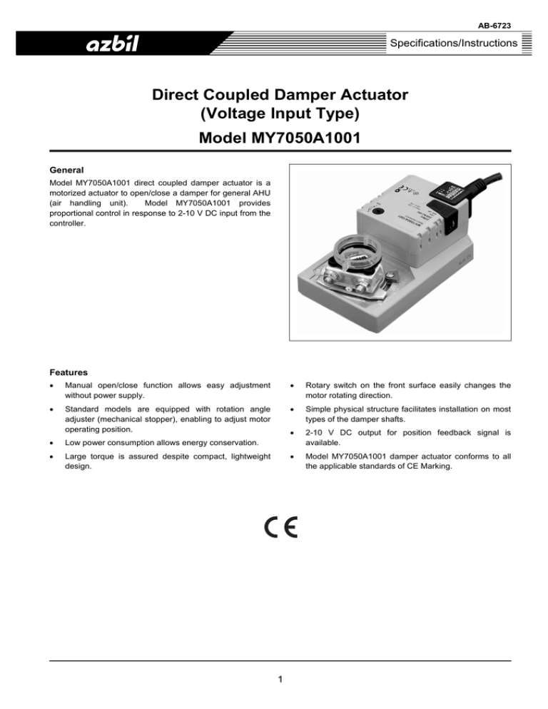
AB-6723 Specifications/Instructions Direct Coupled Damper Actuator (Voltage Input Type) Model MY7050A1001 General Model MY7050A1001 direct coupled damper actuator is a motorized actuator to open/close a damper for general AHU (air handling unit). Model MY7050A1001 provides proportional control in response to 2-10 V DC input from the controller. Features • Manual open/close function allows easy adjustment without power supply. • Rotary switch on the front surface easily changes the motor rotating direction. • Standard models are equipped with rotation angle adjuster (mechanical stopper), enabling to adjust motor operating position. • Simple physical structure facilitates installation on most types of the damper shafts. • • Low power consumption allows energy conservation. 2-10 V DC output for position feedback signal is available. • Large torque is assured despite compact, lightweight design. • Model MY7050A1001 damper actuator conforms to all the applicable standards of CE Marking. 1 AB-6723 Safety Instructions Please read instructions carefully and use the product as specified in this manual. Be sure to keep this manual near by for ready reference. Usage Restrictions This product is targeted for general air conditioning. Do not use this product in a situation where human life may be affected. If this product is used in a clean room or a place where reliability or control accuracy is particularly required, please contact Azbil Corporation’s sales representative. Azbil Corporation will not bear any responsibility for the results produced by the operators. • Do not disassemble the product. Electrical shock or equipment damage may occur. • Operate the product within the service life, and avoid application that keeps product operating cycle excessively frequent. Overuse of the product may cause fire or product damage. WARNING • • • • CAUTION Installation and wiring must be performed by qualified personnel in accordance with all applicable safety standards. This product must be operated under the operating conditions (power, temperature, humidity, vibration, shock, installation position, atmospheric condition, etc) specified in this manual to prevent equipment damages. This product must be operated within its rated operating ranges specified in this manual. Failure to comply will cause equipment damages. Do not install the product in a location with high temperature radiation. High temperature radiation may result in an actuator malfunction. • Do not put heavy load on the product. It may get damaged. • All wiring must comply with local codes of indoor wiring and electric installation rules. • This product does not have a power switch. Be sure to provide a power circuit breaker in the power source. • To prevent product damage, always disconnect the power supply from the product before performing any wiring and installation. • Make sure all the wires are tightly connected. Incomplete connection may result in an actuator malfunction. • To prevent personal injury, do not touch the moving part of the product in operation. Personal injury may result. • Dispose of this product as an industrial waste according to the local regulations. Do not recycle all or part of this product. 2 AB-6723 Specifications Item Model number Action Power supply voltage Power consumption Input signal Input impedance Position feedback signal Rotating angle Operating time Torque at the rated voltage Holding torque Ambient operating conditions Transport/storage conditions Enclosure rating Insulation resistance Withstand voltage Cable Material / Color Weight Applicable damper shaft Accessories Auxiliary devices (Separate order is required.) Requirements for order Specification MY7050A1001 Proportional action 24 V AC ± 20 %, 50 Hz/60 Hz 4 VA (in operation) 2 V DC to 10 V DC voltage input 100 kΩ 2 V DC to 10 V DC voltage output, max. 1 mA Max. 95° (mechanical limit) Approx. 150 s 20 N⋅m 16 N⋅m (Torque to hold the damper in a given position) -20 °C to 50 °C, 95 %RH or less (non-condensing) (This product is not rain-proof and thus is for indoor use only.) -20 °C to 60 °C, 95 %RH or less Dust proof and drip-proof equivalent to IEC IP54 (Cable conduit must be facing downward.) Between case and cable: 100 MΩ or higher at 500 V DC Between case and cable: 500 V AC for 1 min., 1 mA or less 2 0.75 mm × 4-cores, 1 m long PC-GF10 / Silver gray Approx. 1.05 kg Circular: φ10 mm to φ20 mm, 42 mm long or longer Square: 10 mm diagonal to 20 mm diagonal, 42 mm long or longer • M4 tapping screws × 2 • Position indicator ring × 1 • Universal bracket × 1 • Installation instruction sheet × 1 • Power transformer: Model AT72-J1 1 • Auxiliary switch (SPDT × 1)* : Model QY6051A1001 1 • Auxiliary switch (SPDT × 2)* : Model QY6051B1001 2 • Mounting bracket for replacement (for replacing Model MY7040A)* : Model Z-SMA • Product model number (Model MY7050A1001) • Auxiliary device model number (if necessary) Notes: ∗1. Multiple auxiliary switches cannot be connected. Connect single auxiliary potentiometer or auxiliary switch. ∗2. Mounting dimensions of Model MY7050A are different from those of Model MY7040A (former model). For replacing Model MY7040A with Model MY7050A, the mounting bracket Model Z-SMA allows no change of the universal bracket mounting position. 3 AB-6723 Dimensions and Parts Identification 63.4 200 66 138.5 23 14.5 100 Maintenance clearance 100 108.5 Maintenance clearance Maintenance clearance 30 100 88 99 5.1 30 97 100.6 37.5 5.2 37.5 25.5 37.5 25.5 23 37.5 3.6 4.2 Figure 1. Dimensions (mm): Damper actuator 4 Maintenance clearance Actuator AB-6723 Universal bracket 12 72 2 pan-head tapping screws (slotted, M4 × 12, 1.4 pitch) equivalent to JIS* B 1115-1976 are attached to the universal bracket. 2 7 Figure 2. Dimensions (mm): Universal bracket 2 5 12 ∗JIS: Japanese Industrial Standards 6 11 4.3 12 180 Parts Identification Position indicator ring Fastening nut M6 screw (width across flats: 10 mm) Shaft clamp Rotary switch (for rotating direction changeover) Rotation angle adjuster (mechanical stopper) Gear release button Figure 3. Parts identification 5 AB-6723 3) With the gear release button pressed , manually rotate the shaft clamp until it is in the position shown in Fig. 6. Then, insert the universal bracket into the slit of the actuator and fix the bracket onto the damper with the two M4 tapping screws. Installation • CAUTION To prevent product damage, always disconnect the power supply from the product before performing installation. 2. Rotate. IMPORTANT: • Avoid application that keeps product operating cycle excessively frequent. • Meet the rotating direction of the actuator with the damper rotating direction. • Tighten the screws so that the actuator is securely assembled with the damper. 1. Press. 3. Insert. Universal bracket M4 tapping screws Installation procedure 1) Figure 6. Attaching the universal bracket Fully close the damper shaft. Rotate to close. 4) Manually rotate the shaft clamp back to the fully closed position with the gear release button pressed. At this time, be sure to leave a clearance (approx. 1 mm) between the shaft clamp and the rotation angle adjuster (mechanical stopper). Using a wrench, tighten the fastening nuts of the shaft clamp to completely fix the actuator. Damper shaft 42 Damper blade in fully closed position 3. Tighten. Damper shaft diameter 10 to 20 mm 2. Rotate to close. 10 to 20 mm 1 mm Figure 4. Damper shaft 2) Fully close the actuator Model MY7050A, and mount it to the damper shaft. Finger-tighten the fastening nuts of the shaft clamp to temporarily fix the actuator. 1. Press. Figure 7. Complete installation of the actuator body 1. Mount. 5) Attach the position indicator ring to the damper shaft so that the tip of the damper blade and the pointer of the indicator ring point to the same direction. Adjust the rotation angle adjuster on the fully open side depending on the damper rotating angle. 2. Finger-tighten. Damper blade and indicator ring in fully closed position Damper blade 1. Attach. Tip of the damper blade Figure 5. Temporal installation of the actuator body 65° 2. Adjust. Pointer of the indicator ring Figure 8. Attaching the position indicator ring 6 AB-6723 Wires Connection Connect the lead wires as follows: 2-10 V DC input + 2-10 V DC output + Model MY7050A1001 1 ⊥ 2 3 4 5 ∼ ∼ Notes: 24 V AC ∗ Lead wire 1 is the common line for power supply and signal transmission. ∗ Insulate the ends of unconnected wire leads. Figure 9. Lead wires connection Connection example for multiple actuators (in parallel operation) Precautions for parallel operation • Confirm the total power supply voltage of the actuators to operate in parallel. • For power line connection, do not connect lead wire 1 of an actuator and lead wire 2 of another actuator. • Due to different operating time, Model MY7050A actuators in operation may not be synchronized. ∼ ⊥ 1 2-10 V DC input 3 2 2 1 5 3 1 5 3 2 5 + Model MY7050A1001 Figure 10. Connection example: Multiple actuators (in parallel operation) 7 AB-6723 Specifications are subject to change without notice. Building Systems Company http://www.azbil.com/ Rev. 1.1 Jun. 2012 AB-6723 (J: AI-6723 Rev. 1.0) Printed in Japan. 8


