920GATLC
User Instructions for
GATICA Commissioning
1.1
GENERAL PRODUCT INFORMATION:
This product may be dimmed with a 0-10V dimming protocol.
GATICA Adjustability Covered in this Guide:
TILT ADJUST - Section 1
SELECTING CHANNELS - Section 2
PROGRAMMABLE WHITE - Section 3
SPOT ADJUSTMENT - Section 4
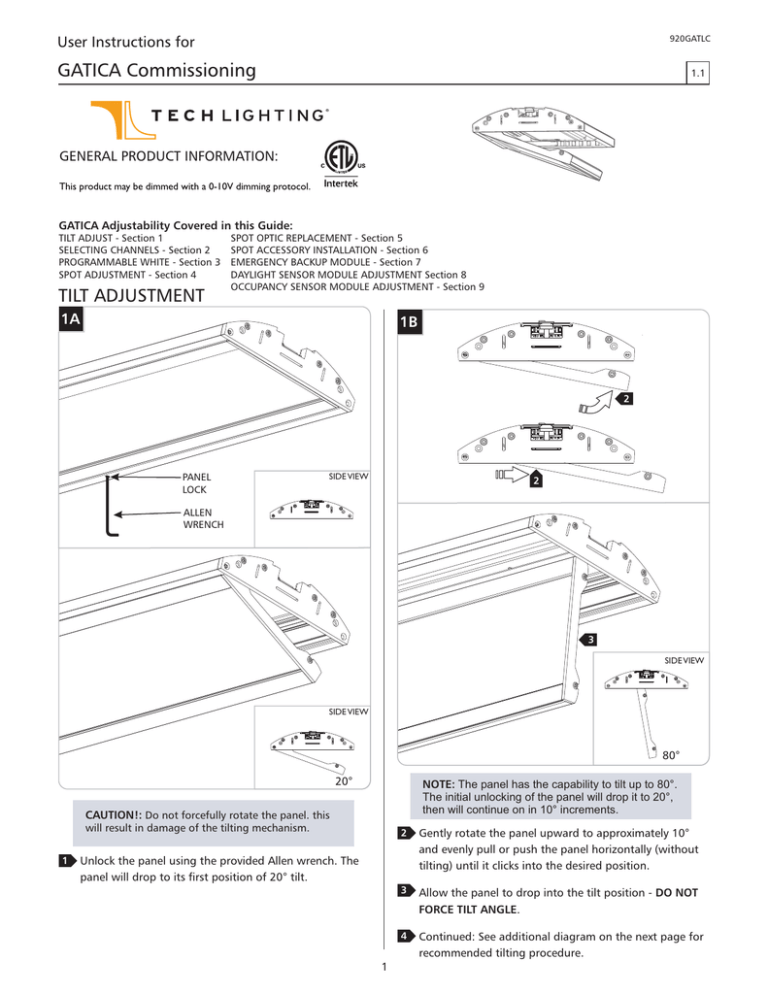
TILT ADJUSTMENT
SPOT OPTIC REPLACEMENT - Section 5
SPOT ACCESSORY INSTALLATION - Section 6
EMERGENCY BACKUP MODULE - Section 7
DAYLIGHT SENSOR MODULE ADJUSTMENT Section 8
OCCUPANCY SENSOR MODULE ADJUSTMENT - Section 9
1A
1B
2
PANEL
LOCK
SIDE VIEW
2
ALLEN
WRENCH
3
SIDE VIEW
SIDE VIEW
80°
20°
NOTE: The panel has the capability to tilt up to 80°.
The initial unlocking of the panel will drop it to 20°,
then will continue on in 10° increments.
CAUTION!: Do not forcefully rotate the panel. this
will result in damage of the tilting mechanism.
1
2
Gently rotate the panel upward to approximately 10°
and evenly pull or push the panel horizontally (without
tilting) until it clicks into the desired position.
3
Allow the panel to drop into the tilt position - DO NOT
FORCE TILT ANGLE.
4
Continued: See additional diagram on the next page for
recommended tilting procedure.
Unlock the panel using the provided Allen wrench. The
panel will drop to its first position of 20° tilt.
1
1C
5
5
5
5
6
6
7
77
70°
20° SLOT
LOCKING SPRING
80°
80°
LOCKING SPRING
30°40°
50°60°
5
Place thumbs on2the side on the fixture and rest the panel between index and middle fingers.
6
Gently lift up using the panel edge, while still lifted, pull the panel towards you. If tilting back up, evenly and gently push
the panel away from you.
7
Allow the panel to gently drop into the desired tilt angle.
8
Ensure that the panel is tilted evenly by checking the locking spring is in the same slot position inside both ends of the
fixture.
NOTE: The rotational degrees can be determined by counting the exposed ticks inside the slot positions. Each slot is
in 10° increments: starting at 20° tilt there are 6 ticks exposed, 30°- 5 ticks, 40°- 4, and so on until the locking spring
is in the final slot at 80° tilt with 0 ticks exposed.
2
Selecting Channels
1
2A
2
3
Programmable White
1
3A
4
CHANNEL
SWITCH
1
SWITCH
POSITION 1
DIMMER 1
(PURPLE)
BRIGHTNESS
CONTROL
DIMMER 2
(PURPLE
WHITE STRIPE)
N/A
DIMMER 3
(PURPLE
BLACK STRIPE)
N/A
CHANNEL 1
DIMMER
CHANNEL 2
DIMMER
3
4
CHANNEL
SWITCH
1
Fixtures in a configuration may be added to distinct
channels to create separate control zones when wired in
accordance to the installation instructions. Using the
channel switch, select the desired zone for each fixture.
DIMMING
MATRIX
2
SWITCH
POSITION 2
N/A
BRIGHTNESS
CONTROL
N/A
SWITCH
POSITION 3
N/A
N/A
BRIGHTNESS
CONTROL
CHANNEL 3
DIMMER
Move the channel switch to the 4 position for all fixtures
with programmable white capabilities. This position
employs channel 1 (purple wire) for brightness control
and channel 2 (purple wire white strip) for color
temperature control. Spot panels will be added to the
dimmer channel only when in position 4.
DIMMING
MATRIX
SWITCH
POSITION 1
SWITCH
POSITION 3
DIMMER 1
(PURPLE)
BRIGHTNESS
CONTROL
N/A
BRIGHTNESS
CONTROL
N/A
COLOR
CONTROL
DIMMER 2
(PURPLE
WHITE STRIPE)
N/A
DIMMER 3
(PURPLE
BLACK STRIPE)
N/A
SWITCH
POSITION4
BRIGHTNESS
CONTROL
CHANNEL 4 DIMMER 2
CCT CONTROL
N/A
CHANNEL 3 DIMMER 3
BRIGHTNESS CONTROL
CHANNEL 4 DIMMER 1
BRIGHTNESS CONTROL
DIMMER 2
SWITCH 2
DIMMER 1
SWITCH 1
DIMMER 1 - BRIGHTNESS
DIMMER 2 - CCT
SWITCH 4
DIMMER 1
SWITCH 1
DIMMER 1 - BRIGHTNESS
DIMMER 2 - CCT
SWITCH 4
DIMMER 3
SWITCH 3
DIMMER 1
SWITCH 1
DIMMER 1
SWITCH 1
DIMMER 2
SWITCH 2
DIMMER 1 - BRIGHTNESS
DIMMER 2 - CCT
SWITCH 4
DIMMER 1
SWITCH 1
DIMMER 3
SWITCH 3
3
Spot Adjustment
Spot Accessory Installation
4A
6A
TILT LOCK
SET SCREW
OPTIC
ALLEN
WRENCH
1
LENS
ACCESSORIES
If tilting the spot, unlock the tilt position by loosening
the tilt lock screw with the provided Allen wrench.
LENS HOLDER
1
To install lens accessories (optional), unscrew the lens
holder from the lamp cartridge, the provided lens and optic
will be seated in the lens holder.
2
Temporarily remove the optic and place a minimum of
1/maximum of 2 accessories into the lens holder.
3
Replace the optic into the lens holder and screw the
assembly back onto the fixture.
4B
Emergency Backup Module
7A
2
Tilt the spot to the desired angle: 0° to 40° tilt capability.
3
Tighten the lock screw to lock the tilt position.
11
4C
4
EM LINE
For emergency battery back up use, connect the red wire
to the building’s “always hot” power line.
Daylight Sensor Module Adjustment
To adjust the setting for the daylight sensor module
using the provided remote control, see instructions on
the manufacturers website:
http://www.wattstopper.com/products/fixture-sensorsand-controls/fixture-sensors/fd-301.aspx#.U71yVfldV9g
Rotate the spot to the desired position: 0-355° rotation
capability.
Occupancy Sensor Module Adjustment
Spot Optic Replacement
To adjust the setting for the occupancy sensor module,
see instructions on the manufacturers website:
http://www.wattstopper.com/products/fixture-sensorsand-controls/fixture-sensors/fs-205.aspx#.U717mvldV9g
5A
SAVE THESE INSTRUCTIONS!
OPTIC
LENS
LENS HOLDER
1
2
To replace the optics, unscrew the lens holder from the
lamp cartridge, the lens and optic will be seated in the lens
holder.
7400 Linder Ave, Skokie, IL 60077
847.410.4400
www.techlighting.com
Remove the old optic, place the new one inside the lens
holder on top of the lens, and screw the assembly back
onto the fixture.
© 2014 Tech Lighting, L.L.C. All rights reserved. The "Tech Lighting" graphic is
a registered trademark of Tech Lighting, L.L.C. Tech Lighting reserves the right
to change specifications for product improvements without notification.
4
A Generation Brands Company


