LED - Delray Lighting
advertisement
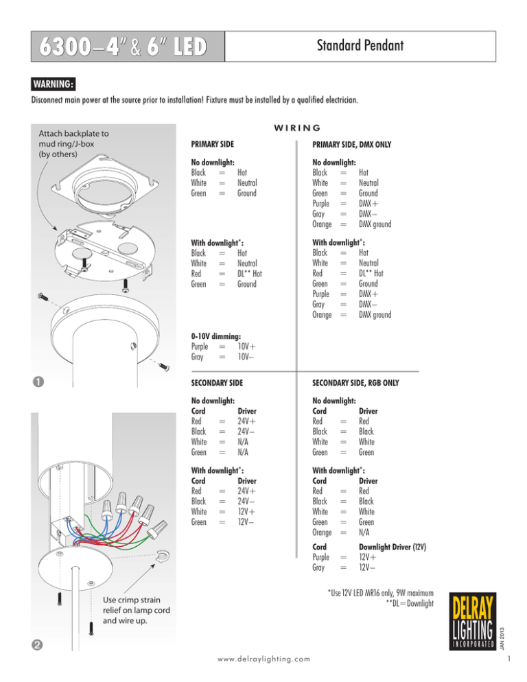
6300–4” & 6” LED Standard Pendant WARNING: Disconnect main power at the source prior to installation! Fixture must be installed by a qualified electrician. Attach backplate to mud ring/J-box (by others) WIRING PRIMARY SIDE PRIMARY SIDE, DMX ONLY No downlight: No downlight: With downlight*: With downlight*: Black =Hot White=Neutral Green=Ground Black =Hot White=Neutral Red = DL** Hot Green=Ground Black =Hot White=Neutral Green=Ground Purple= DMX+ Gray =DMX– Orange = DMX ground Black =Hot White=Neutral Red = DL** Hot Green=Ground Purple= DMX+ Gray =DMX– Orange = DMX ground 0-10V dimming: Purple= 10V+ Gray =10V– ➊ SECONDARY SIDE SECONDARY SIDE, RGB ONLY No downlight: CordDriver No downlight: CordDriver With downlight*: CordDriver With downlight*: CordDriver Red =24V+ Black =24V– White=N/A Green=N/A Red =24V+ Black =24V– White=12V+ Green=12V – Red =Red Black =Black White=White Green=Green Red =Red Black =Black White=White Green=Green Orange= N/A Cord Downlight Driver (12V) Purple= 12V+ Gray =12V – ➋ *Use 12V LED MR16 only, 9W maximum **DL=Downlight JAN 2013 Use crimp strain relief on lamp cord and wire up. w w w. d el r ayl i g hti ng. c o m1 2ww w. del r a yl i ghti ng. c o m CAT5e or CAT6 cable, 568-B color code (by others) For proper operation, confirm that the interface PWM dials remain on the factory preset of channel 1 (001) on all control interfaces, and in all fixture driver housings connected to the Traxon controller. (Standard housing shown.) 4 in. & 6 in. 6300 tube fixtures are prewired to accept CAT5e cable. Up to 31 fixtures may be controlled in a single zone. The control wire (CAT5e cable) must daisy chain to each driver housing for proper control. Traxon DMX controller 6300–4” & 6” LED RJ45 port in RJ45 port in RJ45 port out Traxon Control Wire Path RJ45 port out RJ45 port in RJ45 port JAN 2013 ww w. d el r ayl i g hti ng. c o m3 Zone 2 is the port on the left hand side Zone 1 is the port on the right hand side and Viewed from the rear of the controller, Luminaire Power Supply 1 2 3 4 5 6 7 8 24V 8 Rear View of Traxon Control 1 Power +24VDC white/blue No function No function 5 6 7 No function Power GND 4 8 GND 3 brown white/brown green blue white/green orange DMX + 2 white/orange DMX - 1 Typical 568-B color code (verify) The PIN assignment of the two DMX outputs (female RJ45 ports) is as follows: The unit is powered by an external PSU running at 24 VDC. Power is only supplied via the RJ45 port. The fixtures power supply is prewired for this. Power Supply for Traxon Controller Traxon DMX controller 120 - 277V 6300–4” & 6” LED White Green Red NOTE: If all colors are not working, check the output side of the DMX interface for loose connections. If the connections are good, then check the connector on the LED strip inside the fixture. Daisy chain control wires to subsequent fixtures, if applicable. DMX Interface Black Traxon RGB LED Wiring LED’s LED’s JAN 2013 6300–4” & 6” LED Single Color LED Driver Wiring Diagrams WARNING: Disconnect main power at the source prior to installation! Fixture must be installed by a qualified electrician. Without Dimming INPUT 120-277V WHITE (NEUTRAL) DC OUT RED (POSITIVE) BLACK (LINE) LED LED DRIVER DRIVER LED ARRAY BLUE (NEGATIVE) BLACK With Integrated Dimming INPUT 120-277V WHITE (NEUTRAL) DC OUT RED (POSITIVE) BLACK (LINE) LED LED DRIVER DRIVER LED ARRAY BLUE (NEGATIVE) BLACK VIOLET (POSITIVE) 0-10V DIMMING GRAY (NEGATIVE) With Dimming Controller OUTPUT INPUT WHITE (NEUTRAL) LED LED DRIVER DRIVER DC/DC LED DIMMING CONTROLLER DC OUT 120-277V RED (POSITIVE) INPUT BLACK (LINE) BLUE (NEGATIVE) RED (POSITIVE) LED ARRAY BLUE (NEGATIVE) BLACK VIOLET (POSITIVE) 0-10V DIMMING GRAY (NEGATIVE) 1. Read and review all instructions and diagrams prior to installation. 4. Wire the luminaire following the wiring diagram on the ballast, or inside the box. Use UL listed wire connectors suitable for the size, type, and number of conductors. No loose strands or wires should be present. Secure wire connectors with UL listed electrical tape and wire nuts. 2. Disconnect power prior to installation. Turn off circuit breaker or remove fuse from fuse panel. (Turning off the light switch is insufficient to safeguard against electric shock.) 5. Install lamps (not included). Do not exceed recommended wattage. 3. Electrical connections must conform to local codes and ordinances, or the National Electrical Code. NOTE: These safeguards and instructions are not intended to cover all possible conditions and circumstances. Proceed with caution; utilizing established professional electrical installation methods, tools, and supplies. 6. Restore electricity and test fixture. 4w w w.d el r ayl i g hti ng. c o m JAN 2013 WARNING Risk of fire or electric shock. Only qualified, licensed electricians should install Delray Lighting products.
