8-Button Override Panel Installation Instructions
Description
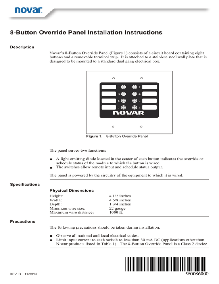
Novar’s 8-Button Override Panel (Figure 1) consists of a circuit board containing eight
buttons and a removable terminal strip. It is attached to a stainless steel wall plate that is
designed to be mounted to a standard dual gang electrical box.
Figure 1.
8-Button Override Panel
The panel serves two functions:
§
§
A light-emitting diode located in the center of each button indicates the override or
schedule status of the module to which the button is wired.
The switches allow remote input and schedule status output.
The panel is powered by the circuitry of the equipment to which it is wired.
Specifications
Physical Dimensions
Height:
Width:
Depth:
Minimum wire size:
Maximum wire distance:
4 1/2 inches
4 5/8 inches
1 3/4 inches
22 gauge
1000 ft.
Precautions
The following precautions should be taken during installation:
§
§
REV. B
11/30/07
Observe all national and local electrical codes.
Limit input current to each switch to less than 30 mA DC (applications other than
Novar products listed in Table 1). The 8-Button Override Panel is a Class 2 device.
560086000
8-Button Override Panel Installation Instructions
Wiring the Module
The override panel’s terminal strip provides room for nine connections:
§
§
One connection for each of the eight buttons on the panel
A ninth common connection
The terminal strip can be removed to facilitate wiring. Figure 2 provides a schematic
diagram of the remote override circuit board.
Te r m i n a l S t r i p
1
2
Figure 2.
3
4
5
6
7
8
9
COM
Wiring schematic. All resistor values are in ohms ±5%.
Table 1 lists a variety of Novar products and indicates the remote override terminal
connections for each. For more details about making the connections, refer to the
installation instructions supplied with each product.
The length of time the override remains in effect varies, depending on how it is specified
in the software for each product.
Table 1. Remote Switch Wiring Connections
NOVAR PRODUCT
REMOTE OVERRIDE TERMINAL CONNECTIONS
Executive Controller (EC)
Terminals 23–38 as appropriate
Input/Output Module (IOM/2)
Terminals 1–8 and GND as appropriate
NCH-1000
Terminals 1–8 and GND as appropriate
Savvy
Terminals 23–38 as appropriate
Space has been provided on the label on the front of the remote override panel so that
each switch can be labeled to indicate the product to which it has been wired.
Mounting the
Panel
The following procedure should be used to mount the panel.
Step
2
Procedure
1
Position the module over the electrical box, aligning the screw holes on the
panel’s plate with those in the box.
2
Insert and tighten the mounting screws (provided) to secure the module.
560086000
Rev. B
11/30/07
8-Button Override Panel Installation Instructions
Checking the
Installation
Once the wiring has been completed and the panel has been mounted, if the panel and the
equipment to which it has been wired are operating properly, the LED in the center of the
remote override button should flash on when an override is in effect.
Part Number
The part number shown in Table 2 should be used to order the necessary Novar part.
Table 2. Novar Part Numbers
PRODUCT
MODEL NO.
8-Button Override Panel
—
PART NO.
780026000
The material in this document is for information purposes only. The contents and the product it describes are
subject to change without notice. Novar makes no representations or warranties with respect to this document.
In no event shall Novar be liable for technical or editorial omissions or mistakes in this document, nor shall it be
liable for any damages, direct or incidental, arising out of or related to the use of this document. No part of this
document may be reproduced in any form or by any means without prior written permission from Novar.
Printed in Mexico.
Copyright © 2007 by Honeywell International, Inc.. All Rights Reserved.
Novar; 6060 Rockside Woods Blvd., Cleveland, OH 44131
Tel.: 800.348.1235
www.novar.com
560086000
Rev. B
11/30/07
3
8-Button Override Panel Installation Instructions
Notes
4
560086000
Rev. B
11/30/07

