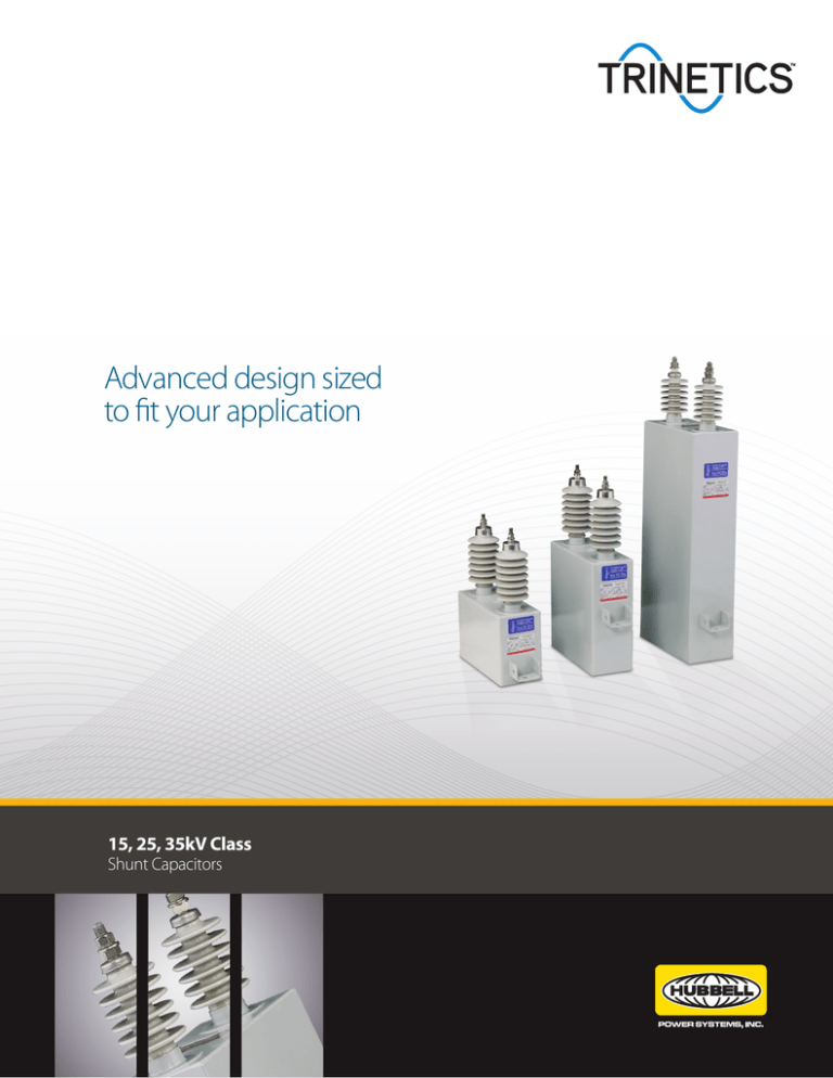
Advanced design sized
to fit your application
15, 25, 35kV Class
Shunt Capacitors
The high performance, high reliability solution.
The Trinetics family of shunt power factor capacitors
incorporate features for top performance and high field
reliability, including polypropylene film and foil element
construction, rugged stainless steel cases protected
with multi-coat epoxy finishes, and heavy-duty
terminals with bolt-down connectors.
Externally fused ratings (standard):
50–600kVAR, 2.4–19.92kV
Shunt capacitors are ideal for applications requiring
power factor correction, voltage regulation and
loss reduction.
• 50 through 400kVAR standard; other sizes available
Internally fused ratings (optional):
100–750kVAR, 2.4–14.62kV
• For distribution and substation applications
• Conforms with IEEE-18/IEC60871-1
• Current technology design includes all polypropylene
film, foil element construction, stainless steel
enclosure, and non-PCB dielectric fluid
• Proven reliable performance
• High current withstand capability
Configurations
•
•
•
•
1- or 2-bushing designs
50, 100, 150, 200, 300, 400kVAR standard sizes
500, 600kVAR and other sizes available*
95, 110 or 125kV BIL (150kV BIL upon request)
*Note: Custom kVAR ratings for power factor correction and
harmonic filter bank applications are available.
Construction
• 409 series stainless steel case
• Finish allows superior heat dissipation and offers excellent
protection against corrosion in outdoor environments
• Sand blasted prior to painting
• Epoxy primer and two coats of polyurethene top coat
• Paint thickness exceeds 85 microns
• Welded terminals are mechanically stronger and provide more
consistent mounting than soldered terminals
• Heavy-duty bolted connections provide superior performance
to tab-and-crimp
• Solid stud eliminates inconsistencies associated with
solder-filled studs
Applications
•
•
•
•
•
Distribution and substation
Pole or pad banks
Power capacitor banks
Metal enclosed banks
Harmonic filter banks
Technical Specifications
Bushing
Applicable standards:
IEEE-18/IEC60871-1
Material:
Wet process porcelain
Rated voltage range:
2 to 22kV
Standard creepage (min):
14.96” (380 mm) up to 15kV (95kV BIL)*
Rated kVAR range:
50kVAR to 750kVAR
Phases:
1 Ph/3 Ph
23.6” (600mm) up to 24 kV (110 or 125kV BIL)
30” (762 mm) for 150kV BIL upon request
Rated frequency:
60Hz or 50Hz
Special creepage:
30” (762 mm) (upon request)
Fuse protection:
External (optional internal fuses)
Insulation level:
95kV or 110kV up to 15kV
Discharge device:
Internally fitted discharge resistor
(1.2 x 50 µ sec wave):
125kV or 150kV up to 24kV
Dielectric type:
All polypropylene film
Impregnating oil:
Non-PCB, non-toxic oil
Ground connection:
Unpainted area under mounting bracket
Case material:
Stainless steel 409 series/CRCA
Paint:
Gray ANSI-70 polyurethene paint suitable for outdoor
application
Permissible overloads
Current:
180%
Voltage:
110%
kVAR
135%
Capacitance tolerance:
Per respective standard
Weight:
Unit specific
Temperature category:
-40°C (-40°F) to +55°C (130°F)
Routine over voltage test:
4.3 times rated voltage DC
*If using an 18kV, 450mm bushing for 95kV BIL, total height of 95kV BIL
capacitors will be increased by one inch.
Performance Curves
Capacitance vs. Temperature
Losses vs. Temperature
1.03
0.30
Losses (W/kVAR)
Connecting lead
C/C20 (P.U.)
1.02
1.01
1.00
0.99
0.20
0.10
0.98
0.97
Internal discharge device
-50 -40 -30 -20 -10 0 10 20 30 40 50
0.00
-50 -40 -30 -20 -10 0 10 20 30 40 50 60
Temperature OC
Temperature OC
Internal fuses
Probability of Case Rupture Curve
Tinned band
Capacitor element
NOTE: Minimum i2t for 100kVAR and larger capacitors is 3,500,000
Amps2seconds for fault currents less than 10,000 amperes.
Capacitor Dimensions
D
Class
kV BIL
kV
A
15kV
95
7.62
15kV
110
7.62
25kV
125
14.4
35kV
150
19.92
kVAR
200
400
200
400
200
400
200
400
A
13.7
13.7
13.7
13.7
13.7
13.7
13.7
13.7
B
5.83
6.69
5.83
6.69
5.83
5.83
5.83
5.83
C
9.06
9.06
9.06
9.06
9.06
9.06
9.06
9.06
D
15.63
15.63
15.63
15.63
15.63
15.63
15.63
15.63
E
14.37
22.13
14.37
22.13
14.96
26.38
15.35
27.56
F
23.81
31.57
25
32.76
26.38
37.8
26.77
38.98
G
16.69
22.82
17.88
22.82
18.5
22.82
18.5
22.82
H
7.24
13.39
7.24
12.21
7.09
11.42
7.09
11.42
I
7.12
8.74
7.12
9.92
7.87
14.96
8.27
16.14
B
C
G
H
F
E
I
NOTE: Dimensions are approximate and subject to change without notice.
Capacitor Components
Terminal connectors
Bushings
Internal fuses (optional)
Built-in discharge system
Capacitor element stacks
Nameplate
Mounting bracket
Stainless steel case
Fusing Options
S
External fuse
S
Capacitor bushing
Discharge device
S S S S S S S S S S S S
S S S S S S S S S S S S
Capacitor elements
S S S S S S S S S S S S
Internal fuses
S S S S S S S S S S S S
Internal Fuse
©2013 Hubbell Power Systems. All rights reserved. Hubbell, the Hubbell logo are registered trademarks or
trademarks of Hubbell Power Systems. All other trademarks are the property of their respective owners.
SS_01_017_E_0213
External Fuse


