Non-Inverting Op-Amp Tutorial: Configuration & Gain
advertisement

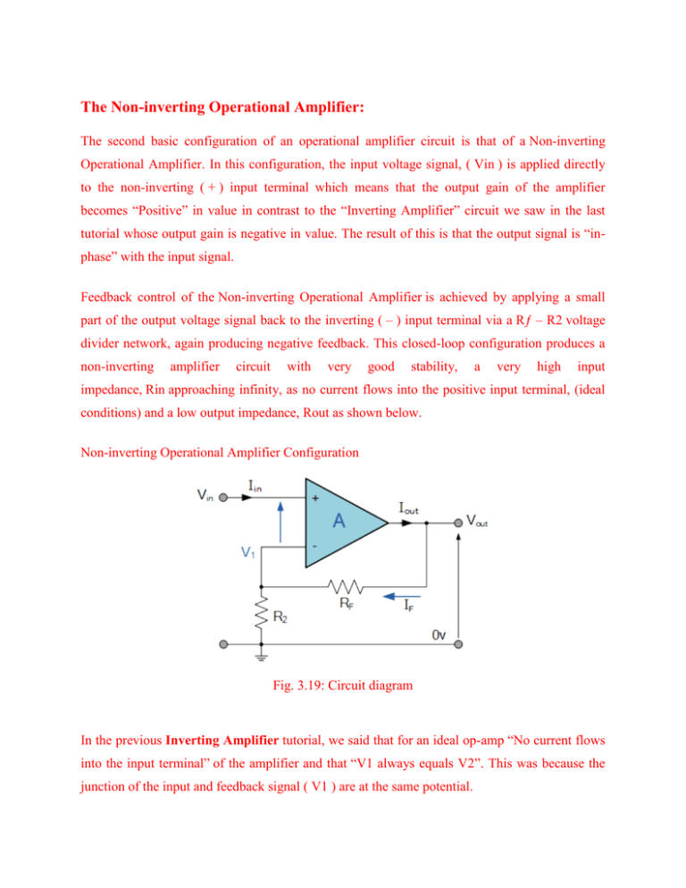
The Non-inverting Operational Amplifier: The second basic configuration of an operational amplifier circuit is that of a Non-inverting Operational Amplifier. In this configuration, the input voltage signal, ( Vin ) is applied directly to the non-inverting ( + ) input terminal which means that the output gain of the amplifier becomes “Positive” in value in contrast to the “Inverting Amplifier” circuit we saw in the last tutorial whose output gain is negative in value. The result of this is that the output signal is “inphase” with the input signal. Feedback control of the Non-inverting Operational Amplifier is achieved by applying a small part of the output voltage signal back to the inverting ( – ) input terminal via a Rƒ – R2 voltage divider network, again producing negative feedback. This closed-loop configuration produces a non-inverting amplifier circuit with very good stability, a very high input impedance, Rin approaching infinity, as no current flows into the positive input terminal, (ideal conditions) and a low output impedance, Rout as shown below. Non-inverting Operational Amplifier Configuration Fig. 3.19: Circuit diagram In the previous Inverting Amplifier tutorial, we said that for an ideal op-amp “No current flows into the input terminal” of the amplifier and that “V1 always equals V2”. This was because the junction of the input and feedback signal ( V1 ) are at the same potential. In other words the junction is a “virtual earth” summing point. Because of this virtual earth node the resistors, Rƒ and R2 form a simple potential divider network across the non-inverting amplifier with the voltage gain of the circuit being determined by the ratios of R2 and Rƒ as shown below. Equivalent Potential Divider Network Then using the formula to calculate the output voltage of a potential divider network, we can calculate the closed-loop voltage gain ( A V ) of the Non-inverting Amplifier as follows: Then the closed loop voltage gain of a Non-inverting Operational Amplifier will be given as: We can see from the equation above, that the overall closed-loop gain of a non-inverting amplifier will always be greater but never less than one (unity), it is positive in nature and is determined by the ratio of the values of Rƒ and R2. If the value of the feedback resistor Rƒ is zero, the gain of the amplifier will be exactly equal to one (unity). If resistor R2 is zero the gain will approach infinity, but in practice it will be limited to the operational amplifiers open-loop differential gain, ( Ao ). We can easily convert an inverting operational amplifier configuration into a non-inverting amplifier configuration by simply changing the input connections as shown. Fig. 3.20: Circuit diagram
